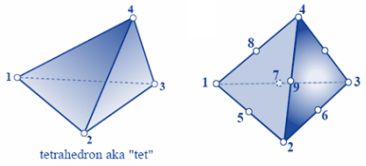
Users:General FEM Analysis/Elements Reference/SolidTetra1
(Created page with 'Category: Users:General FEM == General Description == Topology of SolidTetra1 elements === Element Type === * This eleme…') |
(→General Description) |
||
| (2 intermediate revisions by 2 users not shown) | |||
| Line 4: | Line 4: | ||
[[File:Element_tetra_topo.png|300px|border|up|Topology of SolidTetra1 elements]] | [[File:Element_tetra_topo.png|300px|border|up|Topology of SolidTetra1 elements]] | ||
| − | + | <ref> | |
| + | Pictures taken from the notes to the lecture "Advanced Finite Element Methods for Solids, Plates and Shells" given by Carlos Felippa at the University of Colorado at Boulder. | ||
| + | http://www.colorado.edu/engineering/CAS/courses.d/AFEM.d/ (4th August 2011) | ||
| + | </ref> | ||
=== Element Type === | === Element Type === | ||
| Line 15: | Line 18: | ||
All tetrahedal elements use three translatoric degrees of freedom at each node. <br> | All tetrahedal elements use three translatoric degrees of freedom at each node. <br> | ||
They are named ''Disp_X'', ''Disp_Y'', ''Disp_Z''. | They are named ''Disp_X'', ''Disp_Y'', ''Disp_Z''. | ||
| − | |||
| + | == Input Parameters == | ||
| − | === | + | === Parameter Description === |
{| border="1" cellpadding="3" cellspacing="0" | {| border="1" cellpadding="3" cellspacing="0" | ||
| Line 40: | Line 43: | ||
| − | Example of a | + | === Example of a Complete Input Block === |
<pre> | <pre> | ||
EL-PROP 1: SOLIDTETRA1 | EL-PROP 1: SOLIDTETRA1 | ||
| Line 49: | Line 52: | ||
<pre> | <pre> | ||
! ElementID Part-ID EL-PROP Node-IDs | ! ElementID Part-ID EL-PROP Node-IDs | ||
| − | NEL 1 1 1 1 2 3 4 ! | + | NEL 1 1 1 1 2 3 4 ! 4-noded element |
NEL 2 1 1 20 21 22 23 24 25 26 27 28 29 !10-noded element | NEL 2 1 1 20 21 22 23 24 25 26 27 28 29 !10-noded element | ||
</pre> | </pre> | ||
| − | |||
| − | |||
== Element Loading == | == Element Loading == | ||
Latest revision as of 08:01, 4 August 2011
Contents |
General Description
Element Type
- This element class provides 3D tetrahedal elements with linear (4-noded element) or quadratic shape functions (10-noded)
Degrees of Freedom
All tetrahedal elements use three translatoric degrees of freedom at each node.
They are named Disp_X, Disp_Y, Disp_Z.
Input Parameters
Parameter Description
| Compulsory Parameters | ||
| Parameter | Values, Default(*) | Description |
|---|---|---|
| MAT | EL-MAT int | Linking to a material input block |
| INT_TYPE_TETRA | FULL | Control of integration type Only full inetgration available so far |
| Optional Parameters | ||
Example of a Complete Input Block
EL-PROP 1: SOLIDTETRA1
MAT           = EL-MAT 1
INT_TYPE_TETRA = FULL
Inside the property block there is no distinction between linear and quadratic formulated elements. It is possible to define 4-noded and 10-noded elements using one and the same element property:
 !  ElementID  Part-ID       EL-PROP             Node-IDs
NEL  1           1             1            1  2  3  4                                    ! 4-noded element
NEL  2           1             1            20 21 22 23 24 25 26 27 28 29                 !10-noded element
Element Loading
Tetrahedal elements are able to carry two types of element loads:
- dead load
- temperature load
Dead Load
Dead weight of an element is computed by multiplying material's denisity (ρ) with gravity's acceleration, which has to be defined inside the load block concearning its direction and size.
An example for a load definition of a concrete structure (assuming linear elastic isotropic material behaviour) with gravity acting in positive z-direction would look like
EL-MAT 1 : LIN_ELAST_ISOTROPIC
EMOD=3.5e10  ALPHAT=1e-5  DENS=2.5e3  NUE=0.2
LD-ELEM 1 PART=1
 TYPE=DEAD      D1=0.0   D2=0.0   D3=1.0  VAL=9.81
whereat the finite elemet model is based on SI units (m, N, kg).
Temperature Load
This paragraph only focuses at element specific topics concearing temperature load. For more detailed descriptions please look at the load documentation
For the computation of temperature loads solid elements do not concider any layer of laminate structure within the element. So only the temperature defined for layer number one is considered at each node.
LD-ELEM 1
 TYPE = TEMPERATURE
 ND-SET = 1  LAYER = 1  VAL = +10
 ND-SET = 2  LAYER = 1  VAL = -10
References
- ↑ Pictures taken from the notes to the lecture "Advanced Finite Element Methods for Solids, Plates and Shells" given by Carlos Felippa at the University of Colorado at Boulder. http://www.colorado.edu/engineering/CAS/courses.d/AFEM.d/ (4th August 2011)
| Whos here now: Members 0 Guests 0 Bots & Crawlers 1 |
