Users:Structural Optimization/Design Variables/Nodal Thickness
Contents |
General Description
Short Info
With this design variable, the nodal thickness can be optimized. This is especially usefull in combination with SHELL8 elements since these elements can have a non-constant thickness based on the nodal thicknesses.
The thickness at each node can be initialized in the input file. Alternatively, the initial thickness is computed as the mean thickness of the surrounding elements.
Parameters in the Input File
| Compulsory Parameters | ||
| Parameter | Values, Default(*) | Description |
|---|---|---|
| TYPE | NODE ID, ND-SET ID | Linking to previously defined nodes or node sets |
| SUBTYPE | THICKNESS | To obtain the desired design variable |
| Optional Parameters | ||
| Parameter | Values, Default(*) | Description |
| BOUND | OPT-BOUND ID | Linking to a bound defined in BOUND block.
Remark: only SCALAR_BOUND is valid. |
Example of a Complete Input Block
This design variable can be defined for one node of for a nodal set. It is good practice to add a bound to the thickness design variables to avoid unrealistic values. In general, it is obvious to choose an upper and lower limit. Since the thickness is a scalar design variable, only SCALAR_BOUND is appropriate.
OPT-VAR 1
 TYPE=NODE 100 SUBTYPE=THICKNESS BOUND=OPT-BOUND 1
 TYPE=ND-SET 2 SUBTYPE=THICKNESS BOUND=OPT-BOUND 1
A complete test example
Model description
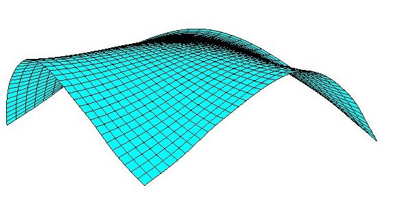
This example considers the thickness optimization of the Kresge auditorium. In a first step, the shape of the auditorium was optimized for minimal strain energy under dead load (cfr. PhD M. Firl) with constant thickness. The resulting shape is presented in the figure. In a second step, the thickness of the optimized shape is optimized. Strain energy under dead load is again used as the objective function. The design variables are the thicknesses at every node, constrained between 0.10 and 0.03 m. The shape of the shell is fixed.

Results
In the figures, the thickness distribution and the Von Mises stresses in the top plane are shown for 50 optimization steps starting from a constant thickness of 0.05 m. It is clear that the largest part of the shell works very efficient on membrane forces and thus the thickness can be the minimal thickness. Only the support regions are subjected to bending, so the stresses can be reduced significantly by increasing the thickness to the maximal thickness.


Input File
to be added
| Whos here now: Members 0 Guests 0 Bots & Crawlers 1 |