Users:General FEM Analysis/Mesh regularization
Contents |
Problem description
Accuracy of finite element computations severely depends on the mesh quality. For this reason,especially within long lasting and mesh disturbing compuataions, it sometimes is necessary to apply certain mesh improving methods, for example in the field of shape optimization.
Currently Carat++ contains two different types of mesh regularization algorithms, Laplace and MSR. Laplace is a purely geometric orientated approach dealing with nodal coordinates only while MSR is mechanically motivated and ends up in the solution of a linear eqaution system.
Although regularization usually is a sub-problem in a bigger context, it can be used directly as a Masterjob in Carat++.
Laplace Regularization
General idea
The concept of Laplace regularization is based on center of gravity computations. The fundamental assumption of this algorithm is that a mesh provoides the best quality when each node is allocated in the cneter of gravity of its neighboring nodes. To this purpose each node computes the center of gravity defined by its neighbors and "moves itsself" to this location. As neighboring relationships are alterning, it is obvious that this algortihm has to run iteratively.
In order to maintain the geometry described by the finite elemnt mesh Laplace regularization distinguishes different types of nodes, each equipted with certain limitations of movement:
- Corner nodes: This nodes are not effected by the algorithm at all
- Line nodes: Each line node is allowed to move allong the tangent defined by its two neighbors (corner nodes or line nodes)
- Surface nodes: A surface node is only allowed to move insie the tangential plane onto the geometry. The tangential plane is defined by the nodal director.
- Volume nodes: Volume nodes are not limited in movement. They directly move into the center of gravity defined by neighboring nodes (volume nodes, surface nodes, line nodes and corner nodes are concidered).
Different sub-methods
Laplace regularization offers two different methods of regularization. The simplified approach works as described above by computing centers of gravity of points. In contrast, a more general approach uses the centers of gravity of neighboring elements instead, whereby each element center is weighted by the element's surface content of volume. This approach is more expensive, but for unstructured and mixed meshes it provides better results.
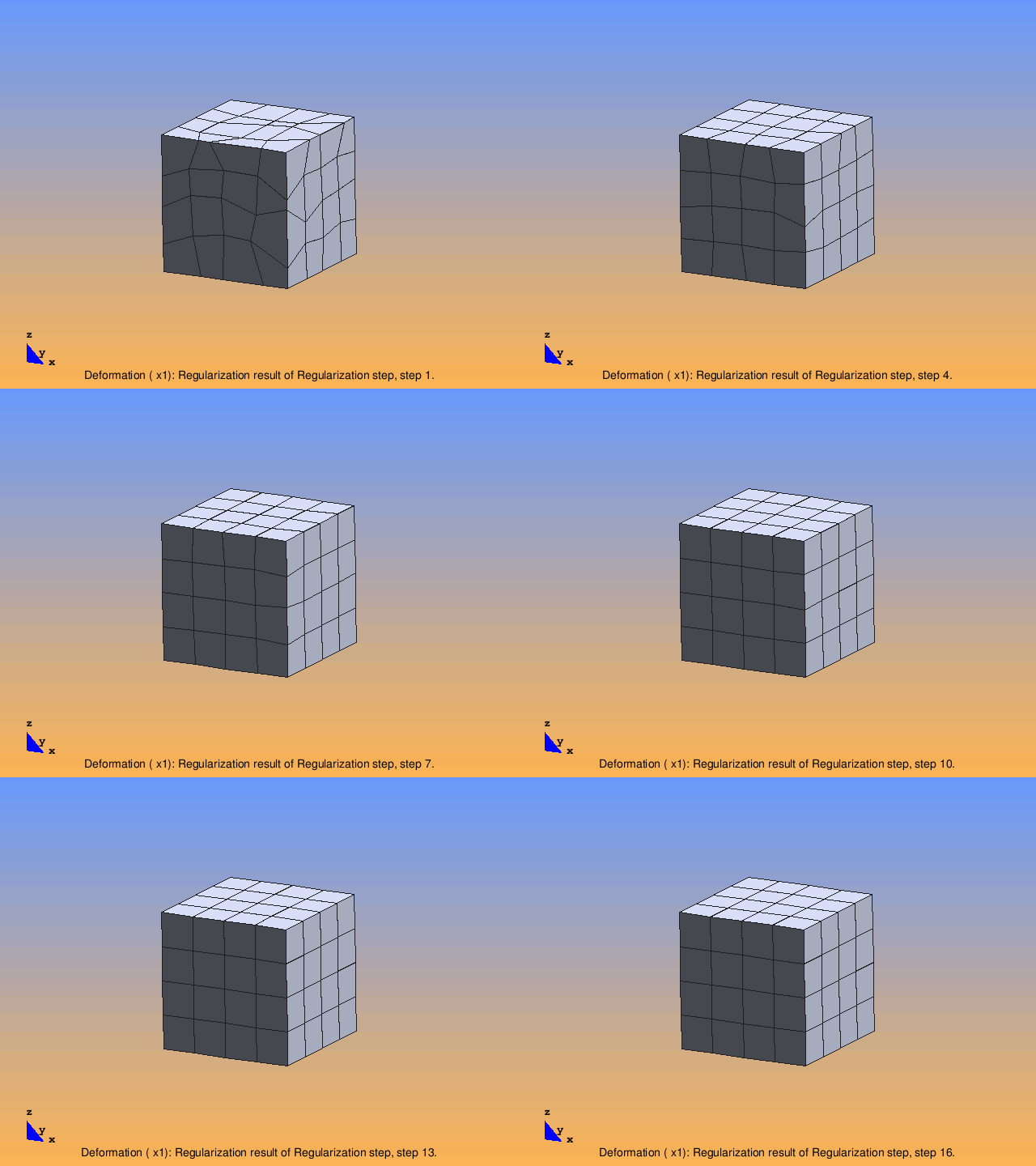
The following animation shows the iterative regularization of a extremely distorted hexahedral body within 15 iterations.
Parameters in the Input File
| Compulsory Parameters | ||
| Parameter | Values, Default(*) | Description |
|---|---|---|
| EL-REGULARIZATION | int, LAPLACE | ID of regularization block |
| DOMAIN | EL-DOMAIN int | Defines the domain which has to be regularized |
| LINE-NODES | ND-SET vector of int | List of node sets that define the line nodes. Use one set per line. Corner nodes are automatically recognized as they belong by definition to two or more lines. |
| SURFACE-NODES | ND-SET vector of int | List of node sets that define the surfaces. Use one set per surface. The definition of a surface includes its bounds (Line and corner nodes) |
| VOLUME-NODES | ND-SET vector of int | Volume nodes are defined here. |
| NMB_STEPS | int | Maximum number of iterations |
| REL_TOLERANCE | real | Demanded relative accuracy for convergence |
| ABS_TOLERANCE | real | Demanded absolute accuracy for convergence |
| Optional Parameters | ||
| AUTOMATIC_NODE_DETECTION | 0(*), 1 | This is an alternative to defining lines, surfaces and edges by hand. If the flag is set to 1 an element topology based algorithm determines automatically model corners, edges and faces. (This part is currently under development. Author: Helles. Date: 09/2010.) |
| USE_SIMPLIFIED_APPROACH | 0(*), 1 | Choose complex regularization (0) based on element centers of gravity or simple approach (1) considering nodes only |
| PERFORM_INEXACT_PARALLEL_REG | int, 0(*) | This parameter can be used in parallel computations only.
If it is set to 0 intermediate results are communicated within one regularization step (which is necessary to obtain the same result as in a serial computation). If it is set to 1 only the final result of an iteration is communicated. Set to n>1 the final result is communicated each nth step only. |
| OUTPUT | PC-OUT int | Each regularization object can be equipted with an output object. This only makes sense (so far) if it is directly used as a master job. |
| OUTPUT_FREQUENCY | int | Specifies the frequency for writing output data. Parameter 'DESIGN_UPDATE' has to be enabled in the output object. |
An exemplary input block
EL-REGULARIZATION 1 : LAPLACE
 DOMAIN = EL-DOMAIN 1
 LINE_NODES = ND-SET 7,8,9,10,11,12,13,14,15,16,17,18
 SURFACE_NODES = ND-SET 1,2,3,4,5,6
 VOLUME_NODES = ND-SET 19
 NMB_STEPS =  200
 REL_TOLERANCE = 0.1
 OUTPUT = PC-OUT 1
Minimum Surface Regularization MSR
| Whos here now: Members 0 Guests 0 Bots & Crawlers 1 |
