Users:General FEM Analysis/Elements Reference/Beam1
Coded, still under development and testing. Missing:
- documentation in Carat++-Wiki
- benchmark-examples
Coming soon
Contents |
General Description
Element Type
- This beam element is a linear 3D-beam taking into account shear deformation (Timoshenko-beam element).
- This beam element has 6 DOFs per node (three translations and three rotations)
Degrees of Freedom
For the Beam1 element use the 3 translatoric degrees of freedom DISP_X, DISP_Y, DISP_Z and the 3 rotatoric degrees of freedom ROT_X, ROT_Y, ROT_Z.
Input Parameters
Parameter Description
| Compulsory Parameters | ||
| Parameter | Values, Default(*) | Description |
|---|---|---|
| MAT | EL-MAT int | Number for the used Material
e.g. MAT=EL-MAT 1 |
| AREA | Definition of the cross-sectional area of the beam | |
| I_YY, I_ZZ | Definition of the moments of inertia | |
| Optional Parameters | ||
Example of a Complete Input Block
EL-PROP 1 : BEAM1
MAT= EL-MAT 1
AREA=5.555  IYY=1.222  IZZ=1.333
KY=1.4   KZ=1.5
Element Loading
Pressure
- not defined yet
Dead Load
- not defined yet
Snow Load
- not defined yet
Theory
The theory and finite element formulation is described in detail in the work of Dieringer [1] and Linhard [2]
For the correct use of the membrane element and the interpretation of related results, the following aspects should be considered:
Material parameter
With the parameter MAT the material, that would be used in the calculation, for the membrane element is defined. A very popular mistake is that a material number would be used, that isn't defined already. Please ensure that the material that you would like to use at this point are already exits. The following materials are testet for the membrane element:
- linear elastic isotropic
- linear elastic orthotropic (Münsch-Reinhardt)
- multilinear elastic isotropic
- elastoplastic isotropic
- material on the basis of response functions
Thickness parameter
The parameter THICKNESS defines the thickness of the membrane. The thickness should be constant over the element.
Prestress directions on the surface
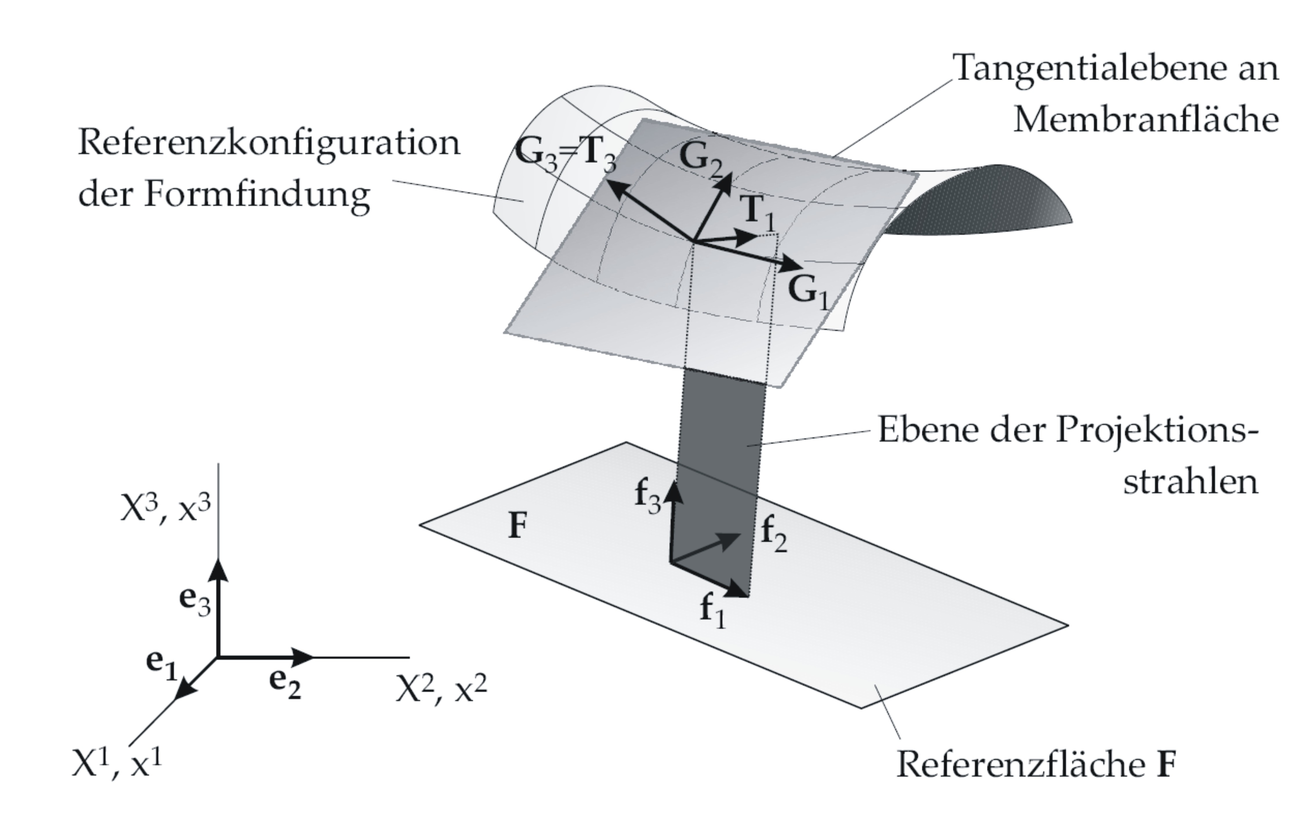
The parameters A_X, A_Y, A_Z and B_X, B_Y, B_Z are used to define the prestress directions on the surface. In this approach the principle directions of the prestress are defined in a plane area (see figure below). The definition of the area is given by the two vectors f1 and f2. The normal vector of the area can be calculated with the cross product of the in plane vectors f3=f1 x f2. Afterwards the line of intersection T1 of the area which is given by f1 and f3 and the curved surface can be calculated. In this approach T1 is interpreted as the first principle direction of the prestress on the curved surface. With the assumption that T3 is equal to the surface normal vector G3 (not uniformed), the second direction of the prestress is calculated as T2=T1 x T3. W.r.t. the parameters for the input file, only the plane area with the vectors f1 and f2 have to be defined. Referring to the depict approach the vector A defines the vector f1 and the vector B defines the vector f2.
Prestress state &sigma
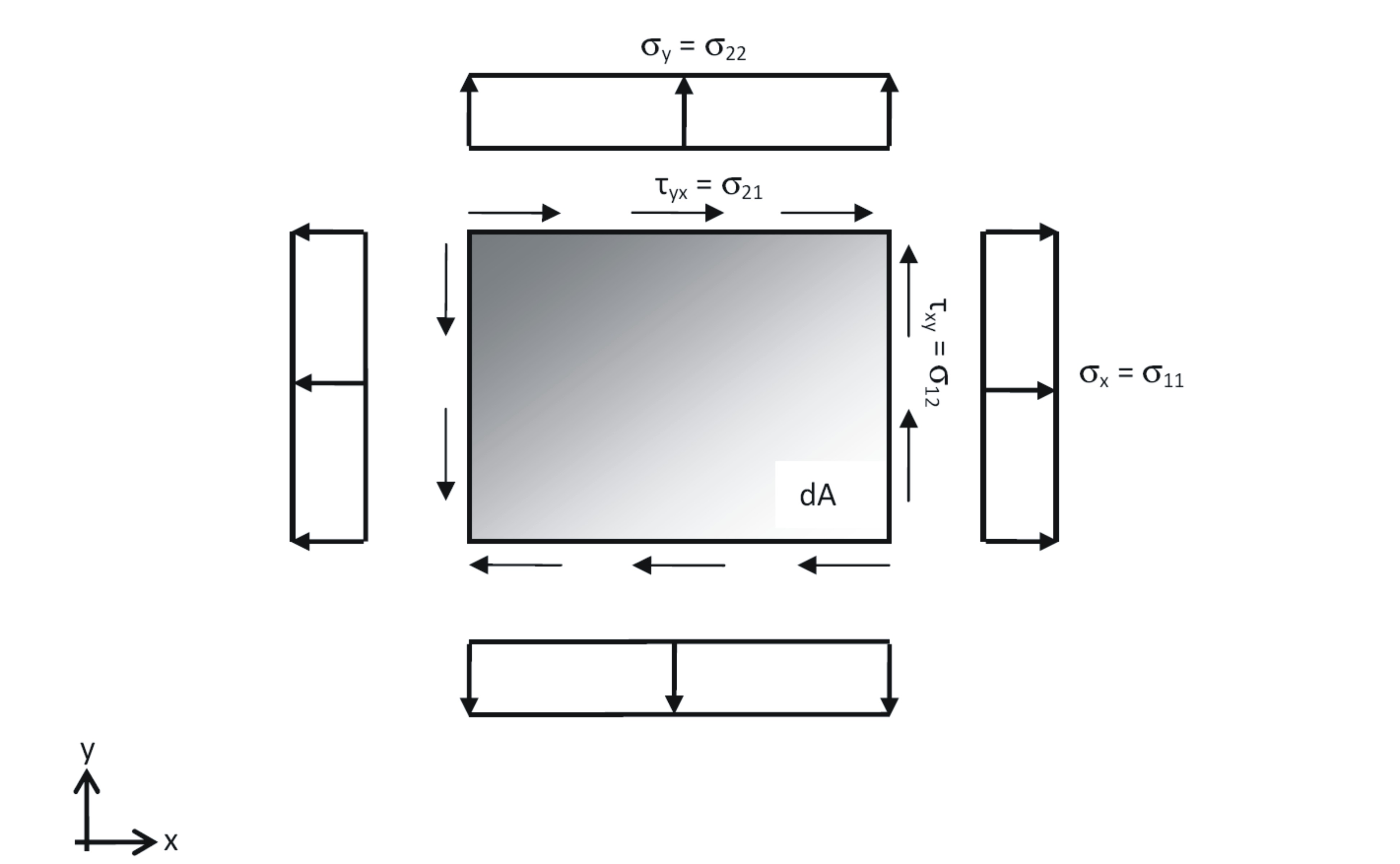
SIG11, SIG22, SIG12 describes the prestress of the membrane element. The element is based on the plane stress assuption. Due to that only normal and shear stresses in the midplane have to be defined. SIGG11 is the stress acting in T1, SIG22 acting in T2 and SIG12 is the in plane shear, whereas SIG12=SIG21 (see figure below).
Lagrange type
With the LARANGE parameter it is possible to switch between form finding and statical/dynamical analysis. For the value UPDATED the element is for form finding and for the value TOTAL the element is for statical/dynamical analysis. It is important that the LANGRANGE parameter match to the type of analysis.
References
- ↑ Dieringer, F.: Implementierung eines geometrisch nichtlinearen Membranelements in einer objektorientierten Programmierumgebung, Masterthesis, Chair of structural analysis, Technische Universität München, 2009
- ↑ Linhard, J.: Numerisch-mechanische Betrachtung des Entwurfsprozesses von Membrantragwerken, PhD-Thesis, Chair of structural analysis, Technische Universität München, 2009
| Whos here now: Members 0 Guests 0 Bots & Crawlers 1 |

