Users:General FEM Analysis/BCs Reference/Dirichlet
Contents |
General Info
Dirichlet conditions can be divided into three groups:
- single point constraints (SPC) which refer to one point only and
- multiple point constraints (MPC) that perform a kind of coupling by applying the same Dirichlet object to several points.
- The RBE condition builds up the last group, which defines a coupling in between several points, but each point computes its own displacement according to a certain formula.
SPC-ZERO
The SPC-ZERO condition is the most frequently used Dirichlet condition. It prescribes zero displacement to certain degrees of freedom of a node. To this purpose it is necessary to list the influenced nodes and the related fixed DOFs inside the Dirichlet block.
BC-DIRICHLET 1 : SPC-ZERO
  NODE 1    DISP_X  DISP_Y   DISP_Z     ! fix all translatoric DOFs for node 1
  NODE 2    DISP_X                      ! only fix the translation in x-direction for node 2
  NODE 3    DIR_DIFF_SHELL8_X           ! the director related degrees of freedom of the SHELL8 can be equipped with Neumann BCs, too
SPC-NONZERO
The SPC-NONZERO condition allows to prescribe a nodal displacement unequal zero (eg. settlement of a support). The handling is quite similar to the SPC-ZERO, but each considered degree of freedom needs to be assigned a value.
REMARK: This BC is currently only available for geometrical non-linear computations.
As an example we regard a cantilever with a prescribed tip displacement of 1.
BC-DIRICHLET 2: SPC-NONZERO NODE 721 DISP_Z = 1 NODE 722 DISP_Z = 1 NODE 723 DISP_Z = 1 |

|
The complete input file can be found in CARAT_ROOT/examples/own_examples/dirichlet_bc/cantilever_spc-nonzero.
SPC-DIRECTION
This condition allows to limit translatoric movements of a point within a plane or a line. To this purpose a plane is defined by the parameter DIRECTION_1 naming the plane normal. If a second plane is defined by specifying DIRECTION_2 the point is only allowed to move an the intersection line of the two planes.
This will be shown on a short example. A truss element defined by nodes 1 and 2 is located along the global x-axis. Point 1 is fixed in all three directions and at node 2 a tensile force is applied. As an additional constraint, node 2 is forced to move along the line defined by the vector (1,1,1). To this purpose, two Dirichlet blocks have to be defined. The first one is a SPC-ZERO block fixing node 1 (not listed here), and the second one limiting node 2 to a one dimensional movement using a SPC-DIRECTION constraint:
BC-DIRICHLET 2: SPC-DIRECTION
  DOFS=DISP_X DISP_Y DISP_Z    NODES=2   DIRECTION_1 = -1,0,1    DIRECTION_2 = 0,1,-1
where the vector (1,1,1) is defined indirectly by two directions being normal to it.
The picture below shows the result with the tip displacement visualized by an arrow. The full input file is available on the SVN server: CARAT_ROOT/examples/own_examples/dirichlet_bc/truss_1elem_spc-zero.

If the same directions have to be applied to several nodes this can either be done by listing the node vector inside the BC-block or by using node sets:
  DOFS=DISP_X DISP_Y DISP_Z    NODES=2,3,4             DIRECTION_1 = -1,0,1    DIRECTION_2 = 0,1,-1
  DOFS=DISP_X DISP_Y DISP_Z    NODE_SETS= NODE-SET 5   DIRECTION_1 = -1,0,1    DIRECTION_2 = 0,1,-1
Another method of prescribing a direction is the usage of the nodal director. It either can be defined in reference or in actual configuration:
  DOFS=DISP_X DISP_Y DISP_Z    NODES=1          DIRECTION = NODE_DIR_REF
  DOFS=DISP_X DISP_Y DISP_Z    NODES=2          DIRECTION = NODE_DIR_ACT
MPC-COUPLING
An instance of MPC-COUPLING allows degrees of freedom of different nodes to share the same equation number, so they assemble to the same entries inside global matrices and vectors and return identical results. Of course only degrees of freedom of the same type can be coupled.
An application for a coupling instance might be the modelling of an hinge. Two nodes are defined at the same coordinates and coupled via their translatoric DOFs:
NODE 1   X 0  Y 0  Z 0
NODE 2   X 0  Y 0  Z 0
   .....
BC-DIRICHLET 1 : MPC-COUPLING
  DOFS = DISP_X  DISP_Y  DISP_Z    NODES=1, 2
Instead of a node list, the nodes to be coupled also can be listed in a node set:
NODE 1   X 0  Y 0  Z 0
NODE 2   X 0  Y 0  Z 0
   .....
ND-SET 1  NAME=NODES2COUPLE
  NODE 1  2

BC-DIRICHLET 1 : MPC-COUPLING
  DOFS = DISP_X  DISP_Y  DISP_Z    NODE_SETS= NODE-SET 1
RBE
If a rigid body element has to be defined, the Dirichlet condition RBE can be used. To this purpose a master node has to be defined which controls the motion of the hole rigid body. All other nodes compute their displacements depending on the translations and rotations of the master node.
The section below shows the definition of a 10-noded rigid body.
BC-DIRICHLET 1 : RBE
  MASTERNODE = NODE 1
  DOFS = DISP_X  DISP_Y  DISP_Z   NODES = 2,3,4,5,6,7,8,9,10
As an example we consider a cantilever loaded by a tip moment. Within the first computation we did not define a rigid body element and so the cantilever curves along its complete length (the red line deviates from the centre line of the green part). For the second run we defined the green part to be a rigid body. As a result, this part does not curve at all (the red line is identical with the centre line).
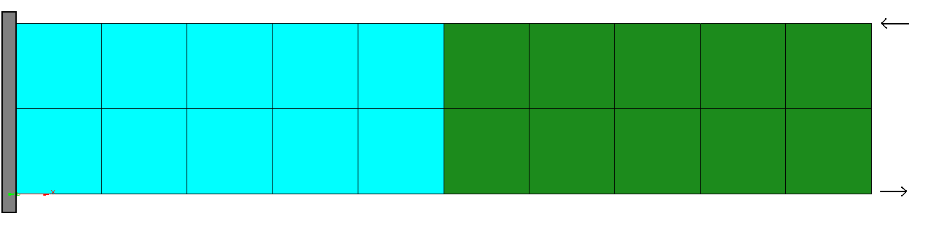
initial geometry
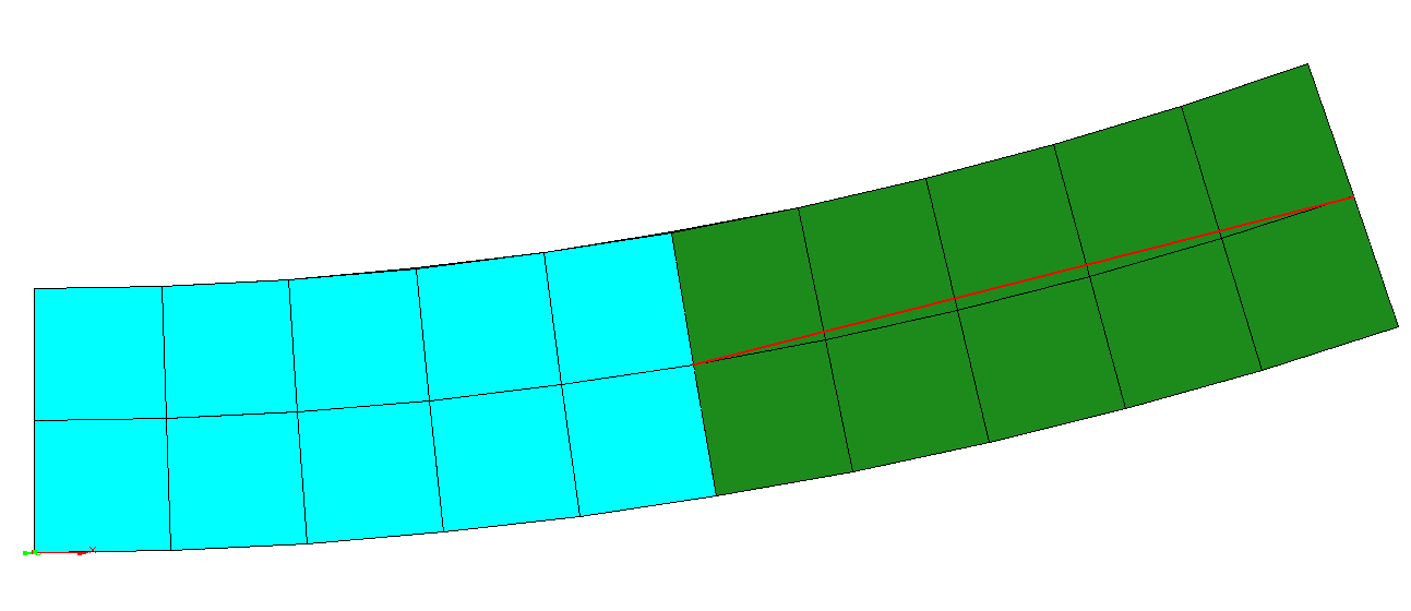
result without RBE
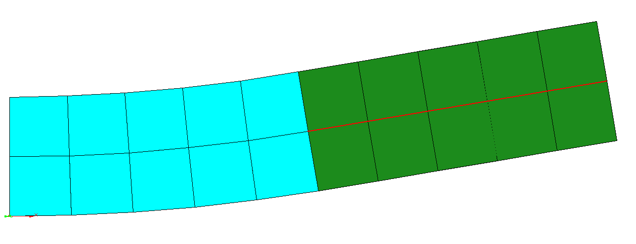
result with RBE defined


| Whos here now: Members 0 Guests 0 Bots & Crawlers 1 |