Users:General FEM Analysis/Materials Reference/Puck Failure Criterion
Contents |
General Description
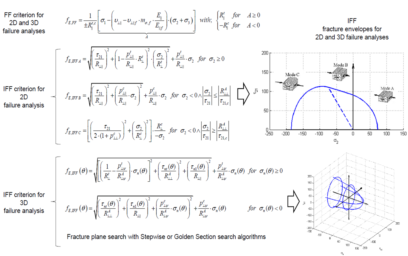
Puck Failure Criterion [1] [2] [3] is based on Mohr‘s fracture hypothesis [4] which is appropriate for brittle fracture behaviour of composite materials. It can distinguish between fibre fracture and different inter-fibre fracture. Both 2D and 3D formulations are implemented into Carat++. Available fracture modes for 2D Puck Criterion are:
- Fibre Fracture (FF)
- Inter Fibre Fracture Mode A (IFF A)
- Inter Fibre Fracture Mode B (IFF B)
- Inter Fibre Fracture Mode C (IFF C)
Available fracture modes for 3D Puck Criterion are:
- Fibre Fracture (FF)
- Inter Fibre Fracture (IFF)
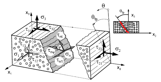
Stresses on the Fracture Plane
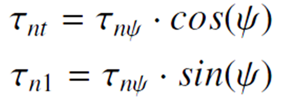
Stresses of the action plane [5]
Strength Analysis
In order to judge if a stress vector on the stress spce is leading to damage, a mathematical expression is needed. This expression is called fracture condition an is written as the following general form:
Ri. : Strengths under corresponding stresses
F : Fracture function
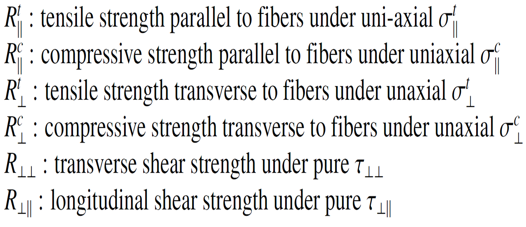
There are 6 main strengths that should be related to the occurring stress state:
The general form of fracture condition can also be rewritten as following:
F < 1 : no fracture
F = 1 : fracture limit reached and fracture occurs
F > 1 : fracture limit exceeded
Parameter Description
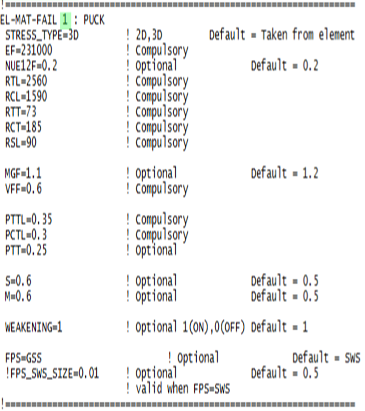
Example of a Complete Input Block
References
- ↑ A. Puck: Festigkeitsanalyse von Faser-Matrix-Laminaten. Hanser, 1996. ISBN 3-446-18194-6
- ↑ H. Deuschle. 3D failure analysis of UD fibre reinforced composites: Puck’s theory within FEA. Phd thesis, Universität Stuttgart, 2010.
- ↑ M. Knops. Analysis of Failure in Fiber Polymer Laminates. Springer Berlin Heidelberg, Berlin, Heidelberg, 2008.
- ↑ O. Mohr. Welche Umstände bedingen die Elastizitätsgrenze und den Bruch eines Materials? (German). Zeitschrift des Vereins deutscher Ingenieure, 24:1524 ff, 1900.
- ↑ M. Knops. Analysis of Failure in Fiber Polymer Laminates. Springer Berlin Heidelberg, Berlin, Heidelberg, 2008.
- ↑ Altug Emiroglu, Master Thesis: Comparative Study of Puck and Tsai-Wu Failure Criteria, Technische Universität München, 2013.
| Whos here now: Members 0 Guests 0 Bots & Crawlers 1 |

