Users:General FEM Analysis/Elements Reference/SolidHexa1
(→The EAS Method) |
|||
| Line 107: | Line 107: | ||
== The EAS Method == | == The EAS Method == | ||
The idea of enhanced assumed strains is to enlarge the element srain field by a set of additional strains in order to enable the element to express certain states of displacement without locking due to parasitic strains. | The idea of enhanced assumed strains is to enlarge the element srain field by a set of additional strains in order to enable the element to express certain states of displacement without locking due to parasitic strains. | ||
| − | <ref name="SiRi90" | + | <ref name="SiRi90"> J.C. Simo, M.S. Rifai: „A class of mixed assumed strain methods and the method |
| − | > J.C. Simo, M.S. Rifai: „A class of mixed assumed strain methods and the method | + | |
of incompatible modes“, in „International Journal for Numerical Methods in Enginee- | of incompatible modes“, in „International Journal for Numerical Methods in Enginee- | ||
ering“, Vol. 29, 1990, pages 1595-1638 | ering“, Vol. 29, 1990, pages 1595-1638 | ||
</ref> | </ref> | ||
| − | <ref name="AnRa93" | + | <ref name="AnRa93"> U. Andelfinger, E. Ramm: „EAS-Elements for two-dimensional, three-dimensional, |
| − | > U. Andelfinger, E. Ramm: „EAS-Elements for two-dimensional, three-dimensional, | + | |
plate and shell structures and their equivalence to HR-Elements“, in „International | plate and shell structures and their equivalence to HR-Elements“, in „International | ||
Journal for Numerical Methods in Engineeering“, Vol. 36, 1993, pages 1311-1337 | Journal for Numerical Methods in Engineeering“, Vol. 36, 1993, pages 1311-1337 | ||
Revision as of 14:29, 3 September 2010
Contents |
General Description
Element Type
- This element class provides 3D hexahedral elements with linear (8-noded element), partially quadratic (20-noded) or quadratic shape functions (27-noded)
- The element formulation includes an enhanmced assumed strain (EAS) improvement in order to avoid locking effects. This feature is only available for 8-noded elements and usage is only recommended in geometrically linear computations.
Degrees of Freedom
All hexahedral elements use three translatoric degrees of freedom at each node.
They are named Disp_X, Disp_Y, Disp_Z.
Input Parameters
Parameter Description
| Compulsory Parameters | ||
| Parameter | Values, Default(*) | Description |
|---|---|---|
| MAT | EL-MAT int | Linking to a material input block |
| INT_TYPE_HEXA | FULL, REDUCED | Control of integration type 20-noded elements are able to perform a uniform reduced integration (2x2x2 instead of 3x3x3) without hourglassing stabilisation |
| Optional Parameters | ||
| Parameter | Values, Default(*) | Description |
| EAS | int | Flag Enhances Assumed Strains (EAS) method Possible values are:
|
Example of a Complete Input Block
EL-PROP 1: SOLIDHEXA1
MAT           = EL-MAT 1
INT_TYPE_HEXA = FULL
EAS           = 0
Inside the property block there is no distinction between linear and quadratic formulated elements. It is possible to define 8-noded, 20-noded and 27-noded elements using one and the same element property (assuming that no EAS is used):
 !  ElementID  Part-ID       EL-PROP             Node-IDs
NEL  1           1             1            1  2  3  4  5  6  7  8                                                                  ! 8-noded element
NEL  2           1             1            20 21 22 23 24 25 26 27 28 29 30 31 32 33 34 35 36 36 38 39 40                          !20-noded element
NEL  3           1             1            50 51 52 53 54 55 56 57 58 59 60 61 62 63 64 65 66 66 68 69 70 71 72 73 74 75 76 77     !27-noded element
Element Loading
Hexahedral elements are able to carry two types of element loads:
- dead load
- temperature load
Dead Load
Dead weight of an element is computed by multiplying material's denisity (ρ) with gravity's acceleration, which has to be defined inside the load block concearning its direction and size.
An example for a load definition of a concrete structure (assuming linear elastic isotropic material behaviour) with gravity acting in positive z-direction would look like
EL-MAT 1 : LIN_ELAST_ISOTROPIC
EMOD=3.5e10  ALPHAT=1e-5  DENS=2.5e3  NUE=0.2
LD-ELEM 1 PART=1
 TYPE=DEAD      D1=0.0   D2=0.0   D3=1.0  VAL=9.81
whereat the finite elemet model is based on SI units (m, N, kg).
Temperature Load
This paragraph only focuses at element specific topics concearing temperature load. For more detailed descriptions please look at the load documentation
For the computation of temperature loads solid elements do not concider any layer of laminate structure within the element. So only the temperature defined for layer number one is considered at each node.
The combination of temperature loading and EAS improvement is possible.
LD-ELEM 1
 sTYPE = TEMPERATURE
 ND-SET = 1  LAYER = 1  VAL = +10
 ND-SET = 2  LAYER = 1  VAL = -10
The EAS Method
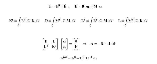
The idea of enhanced assumed strains is to enlarge the element srain field by a set of additional strains in order to enable the element to express certain states of displacement without locking due to parasitic strains. [1] [2].
To this purpose the strain-displacement relation is enlarged by additional terms which leads to a modified element stiffness matrix:
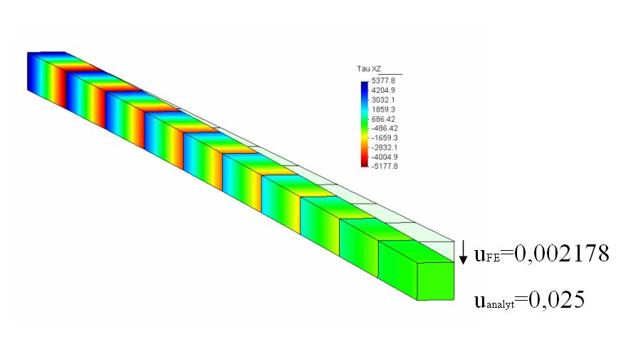
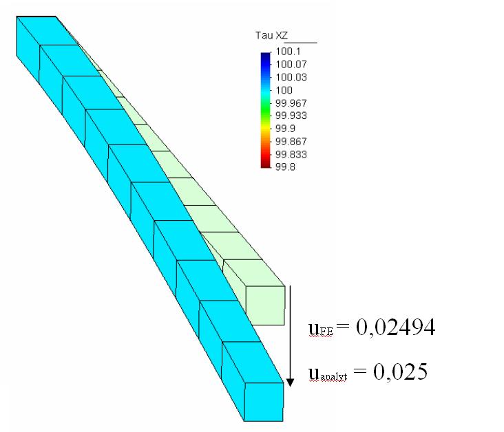
The following example will show the benefit of EAS improved elements toward purely displacment formulated eight-noded hexahedrals. The investigated system is a tip loaded cantilever wherby the cross section is modeled by one element.
The pure displacement based elements show the well known in-plane shear locking which increases along the cantilever with increasing bending moment. As artificial strain/shear produces artificial stiffness, the tip displacement is extremly under estimated.
In contrast the EAS improved elements are able to eliminate artificial strains arrising from locking, and so tip displacement is described correctly.
References
- ↑ J.C. Simo, M.S. Rifai: „A class of mixed assumed strain methods and the method of incompatible modes“, in „International Journal for Numerical Methods in Enginee- ering“, Vol. 29, 1990, pages 1595-1638
- ↑ U. Andelfinger, E. Ramm: „EAS-Elements for two-dimensional, three-dimensional, plate and shell structures and their equivalence to HR-Elements“, in „International Journal for Numerical Methods in Engineeering“, Vol. 36, 1993, pages 1311-1337
| Whos here now: Members 0 Guests 0 Bots & Crawlers 1 |


