Users:General FEM Analysis/Elements Reference/Shell10
| Line 196: | Line 196: | ||
|} | |} | ||
| + | == Benchmarks == | ||
| + | The main benchmark files in the ''Carat++''-repository are | ||
| + | '../examples/benchmark_examples/elements/shell10_quad_CEG/cbm_ScoLoRoof_full_quad_struc_192.dat' | ||
| + | '../examples/benchmark_examples/elements/shell10_quad_CIN/cbm_HemiShell_full_quad_103.dat' | ||
| + | |||
| + | '../examples/benchmark_examples/elements/shell10_tria_CEG/cbm_PinchedCyl_full_tria_240.dat' | ||
| + | |||
| + | '../examples/benchmark_examples/elements/shell10_tria_CIN/cbm_ScoLoRoof_full_tria_struc_384.dat' | ||
| + | |||
| + | '../examples/benchmark_examples/elements/shell10_tria_nonlin/cbm_NONLN_Cyl_tria_8x8.dat' | ||
== References == | == References == | ||
<references/> | <references/> | ||
Latest revision as of 15:16, 12 January 2017
Contents |
General Description
Element Type
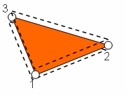
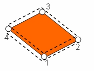
- This shell element is a rotationfree shell element with 3 (external) degrees of freedom per node.
- It has Kirchhoff-Love kinematics.
- Underlying element is the Membrane1 element and additional bending stiffness is added for each dof.
- Curvature information is calculated out of neighboring elements.
File:Patch example-eps-converted-to.pdf
Degrees of Freedom
The degrees of freedom are:
- the 3 translatoric components of the shell midplaine in the global cartesian frame (the 3 "classical" translatoric DOFs): They are named Disp_X, Disp_Y, Disp_Z.
Input Parameters
Parameter Description
Parameter Description
| Compulsory Parameters | ||
| Parameter | Values, Default(*) | Description |
|---|---|---|
| MAT | EL-MAT int | Number for the used Material
e.g. MAT=EL-MAT 1 |
| THICKNESS | int | Thickness of the shell |
| A_X, A_Y, A_Z
B_X, B_Y, B_Z |
Definition of the principle directions of the surface. To define the prestress dirctions. (see Membrane1 element) | |
| SIG11
SIG22 SIG12 |
Prestress state of the membrane. (see Membrane1 element) | |
| CURV_TYPE_SHELL10 | CEG, CIN | Definition of curvature calculation type. CIN for curvature through interpolated normal field. CEG for curvature through enhanced geometry. (see description below) |
| Optional Parameters | ||
Example of a Complete Input Block
EL-PROP 1 : SHELL10
MAT=EL-MAT 1
THICKNESS=0.1
INT_TYPE_SHELL10 = FULL
CURV_TYPE_SHELL10 = CEG
PRESTRESS      SIG11=0.0     SIG22=0.0      SIG12=0.0
A_X=1.0     A_Y=0.0    A_Z=0.0
B_X=0.0    B_Y=1.0    B_Z=0.0
Element Loading
Pressure
Dead Load
Snow Load
Theory
The theory and finite element formulation is originally based on the work of Linhard [1]. A detailled derivation of the presented formulas and additional information to the implementation is shown by Both [2]. A short introduction into theory, modelling aspects and behaviour is given in the following.
Decomposition of virtual work
For the derivation the principle of virtual work ![]() is splitted into membrane and bending parts:
is splitted into membrane and bending parts: ![]() The bending part is calculated with
The bending part is calculated with  consisting out of moments acting on changes of curvature. With an ideal linear elastic material law, e.g. St. Venant-Kirchhoff model, these moments can be related to the change of curvature with:
  . Finally the change of curvature can be calculated with:
 ![]() . The calculation of curvature related quantites on C0-continious meshes is shown next.
. The calculation of curvature related quantites on C0-continious meshes is shown next.
Curvature on C0 continous finite element meshes
While isoparametric triangular elements are flat, quadrilateral elements allready bring a curvature along, but which is not sufficient for the calculation of a surface curvature.
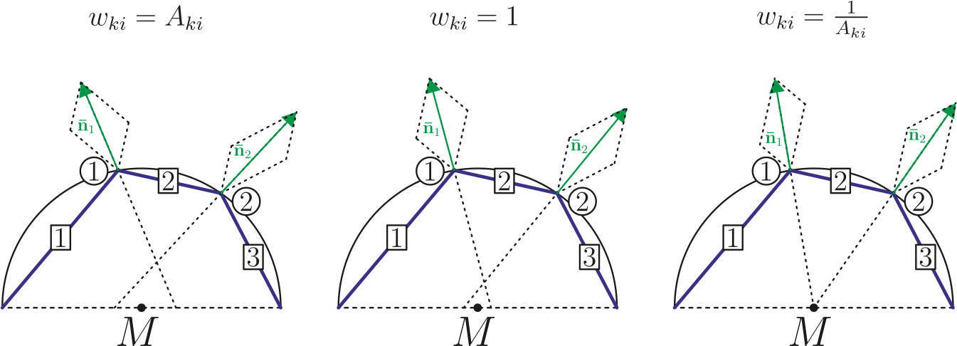
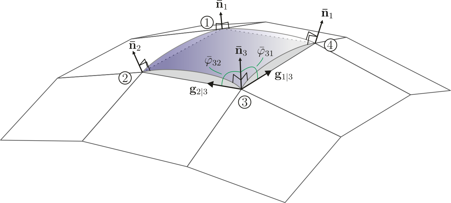
The basic idea is to extend the normal vector at the nodes with information of the neighbouring elements. The so called "nodal director" is the averaged normalized normal vector at each node and calulated with: 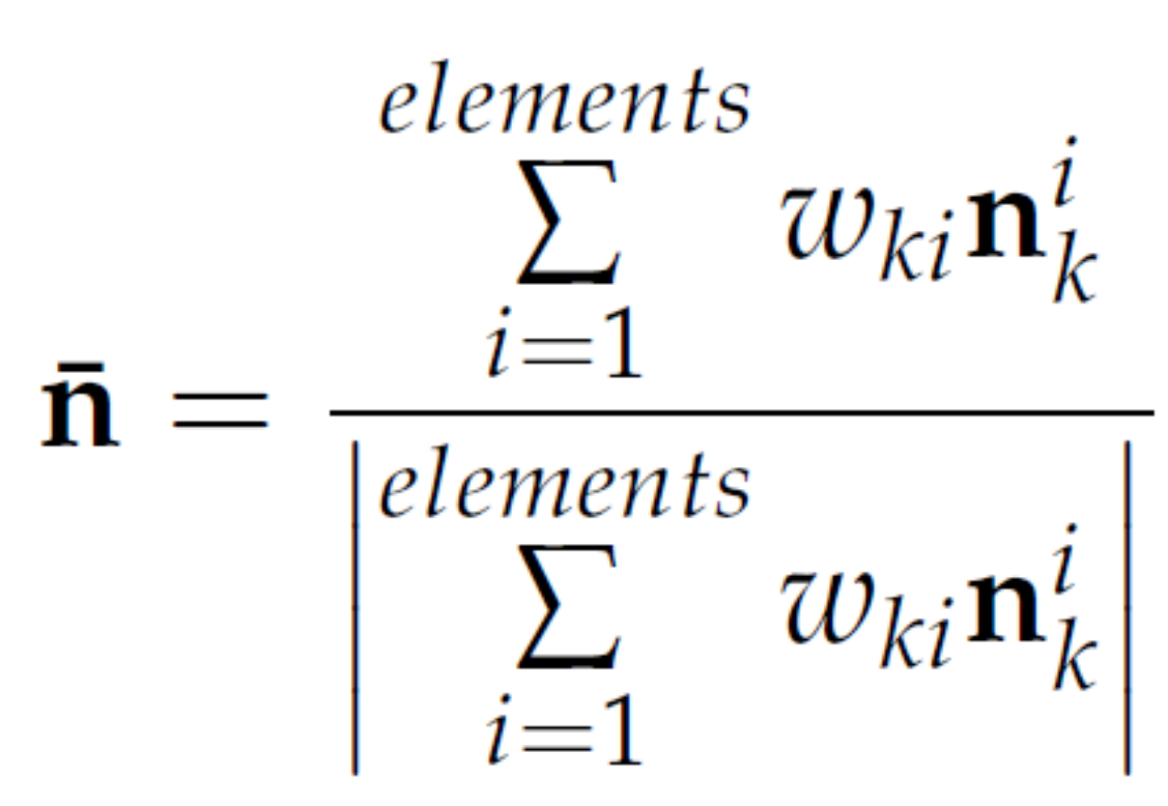 . The weighting factors are the approximated area of the corresponding element. It can be shown that for a two dimensional discretized half-circle these weighting factors exactly reproduce the surface normals.
CIN: curvature through interpolated normal vectors
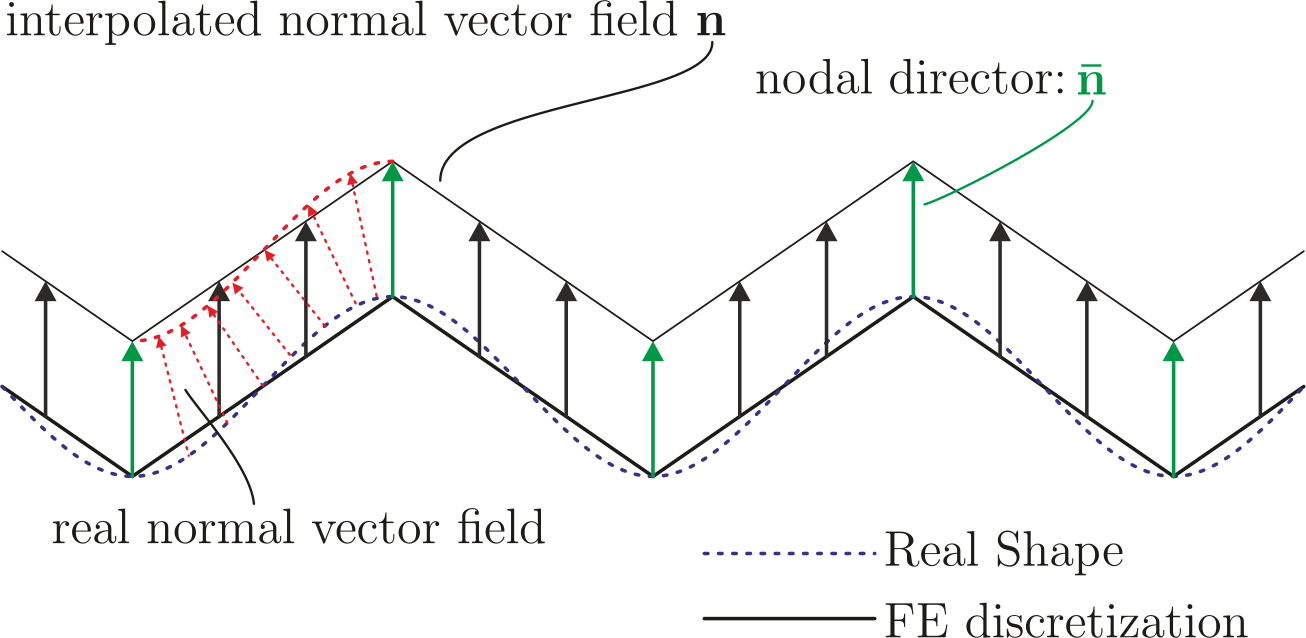
For the curvature calculation the straightforward approach is to use the curvature tensor introduced in classical differential geometry on the discretized geometry. Since the normal vector is needed throughout the whole element the nodal director is interpolated with the same shape functions used for the isoparametric element. This formulation results in a deficiency shown in the following figure.
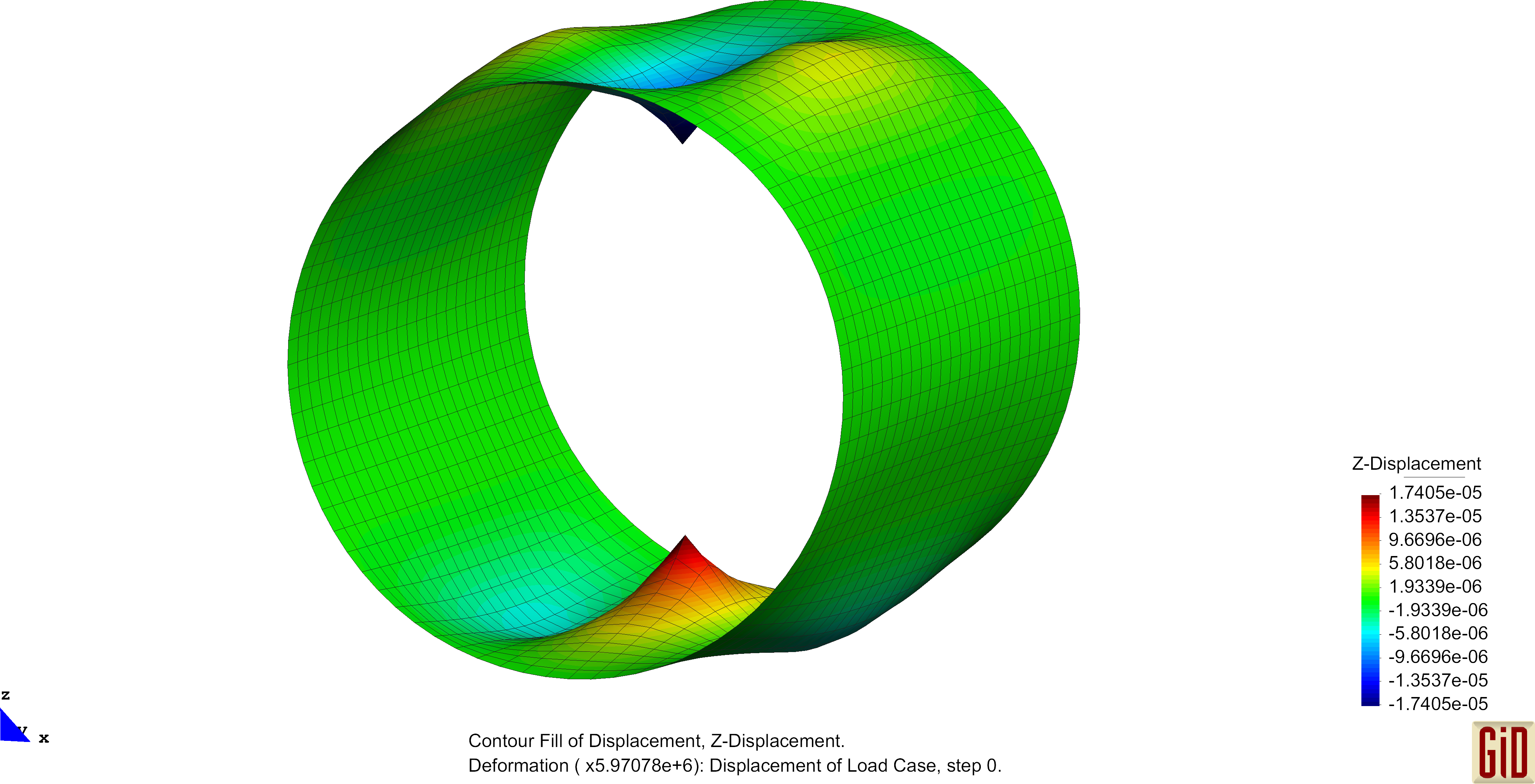
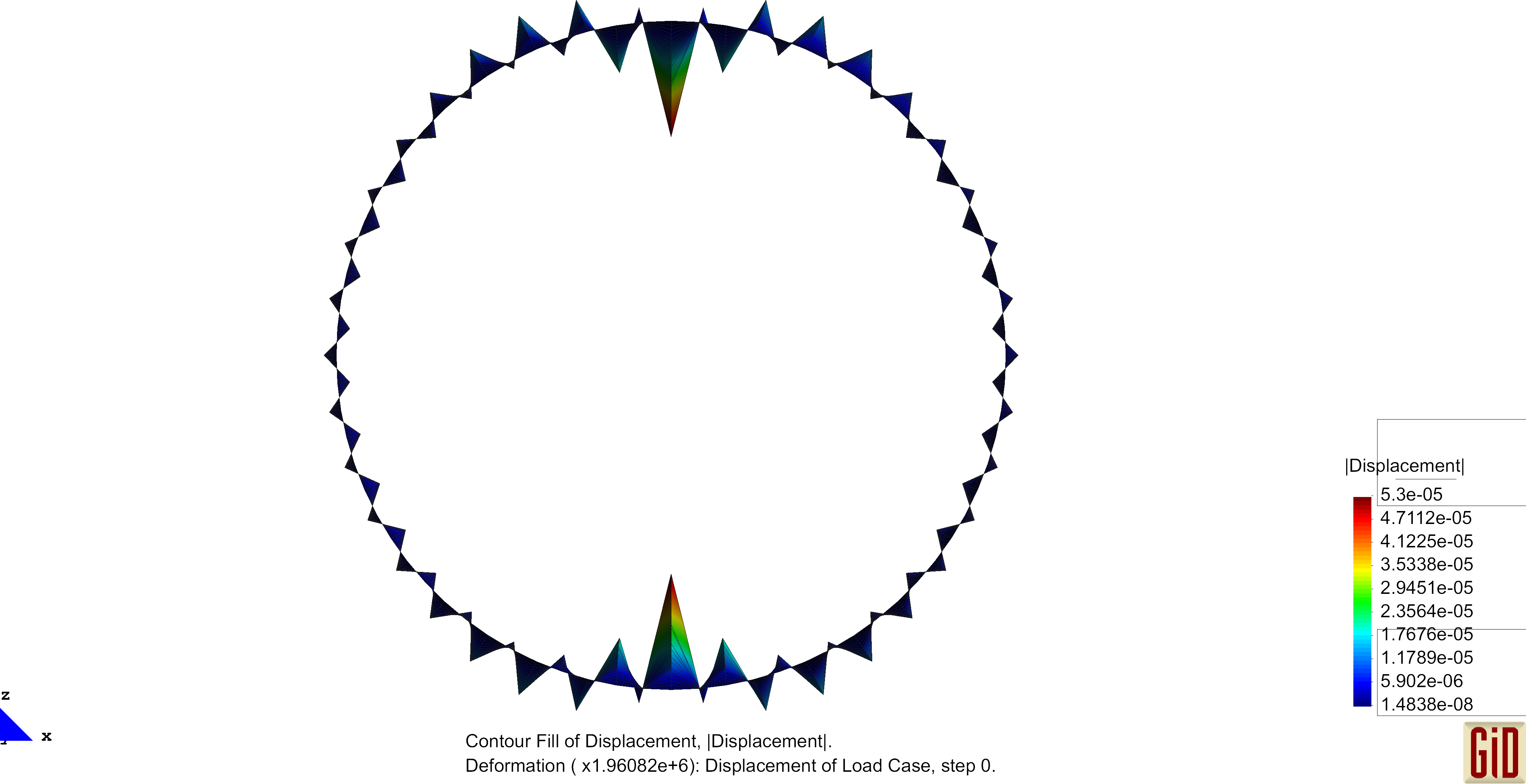
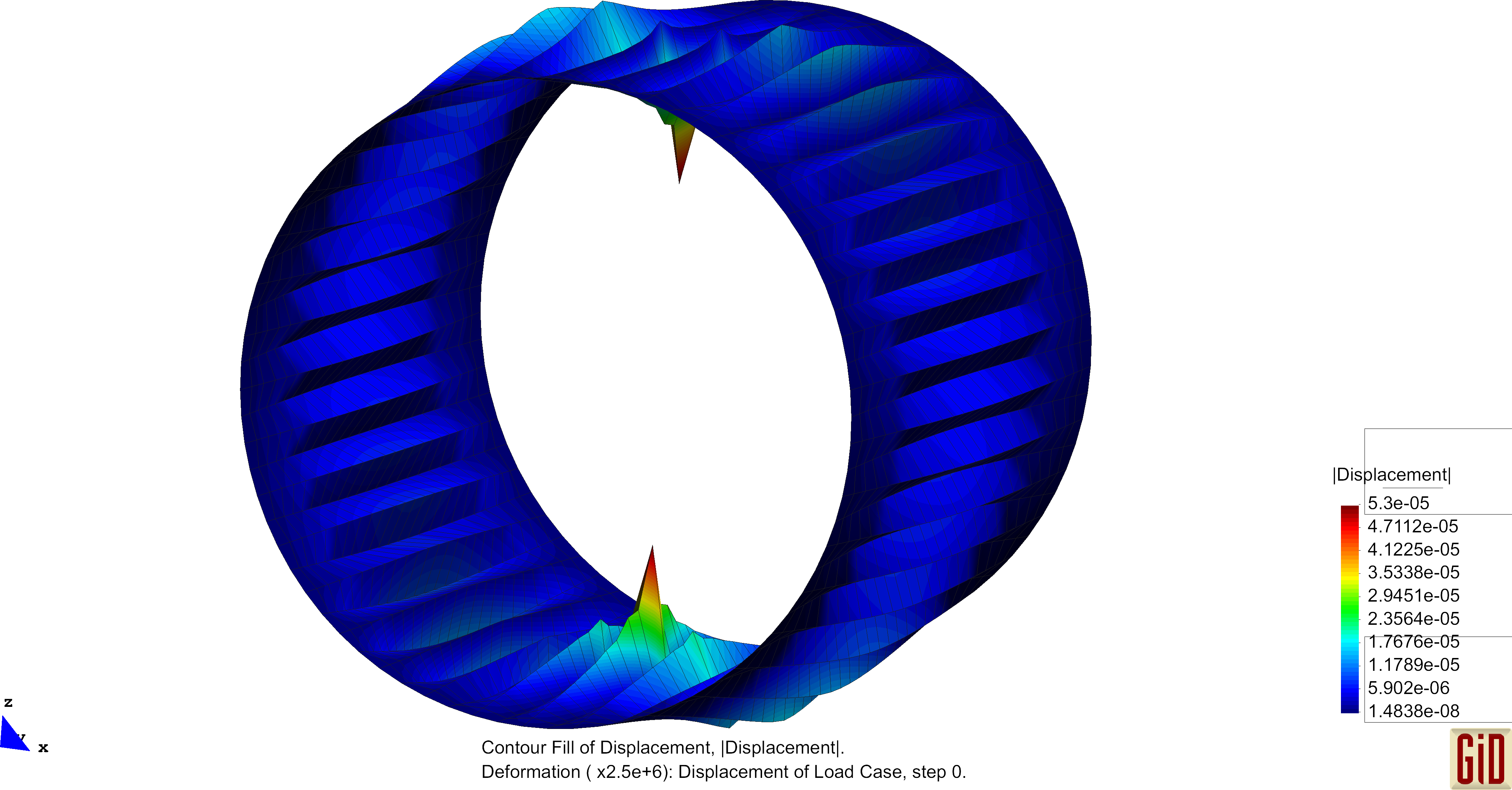
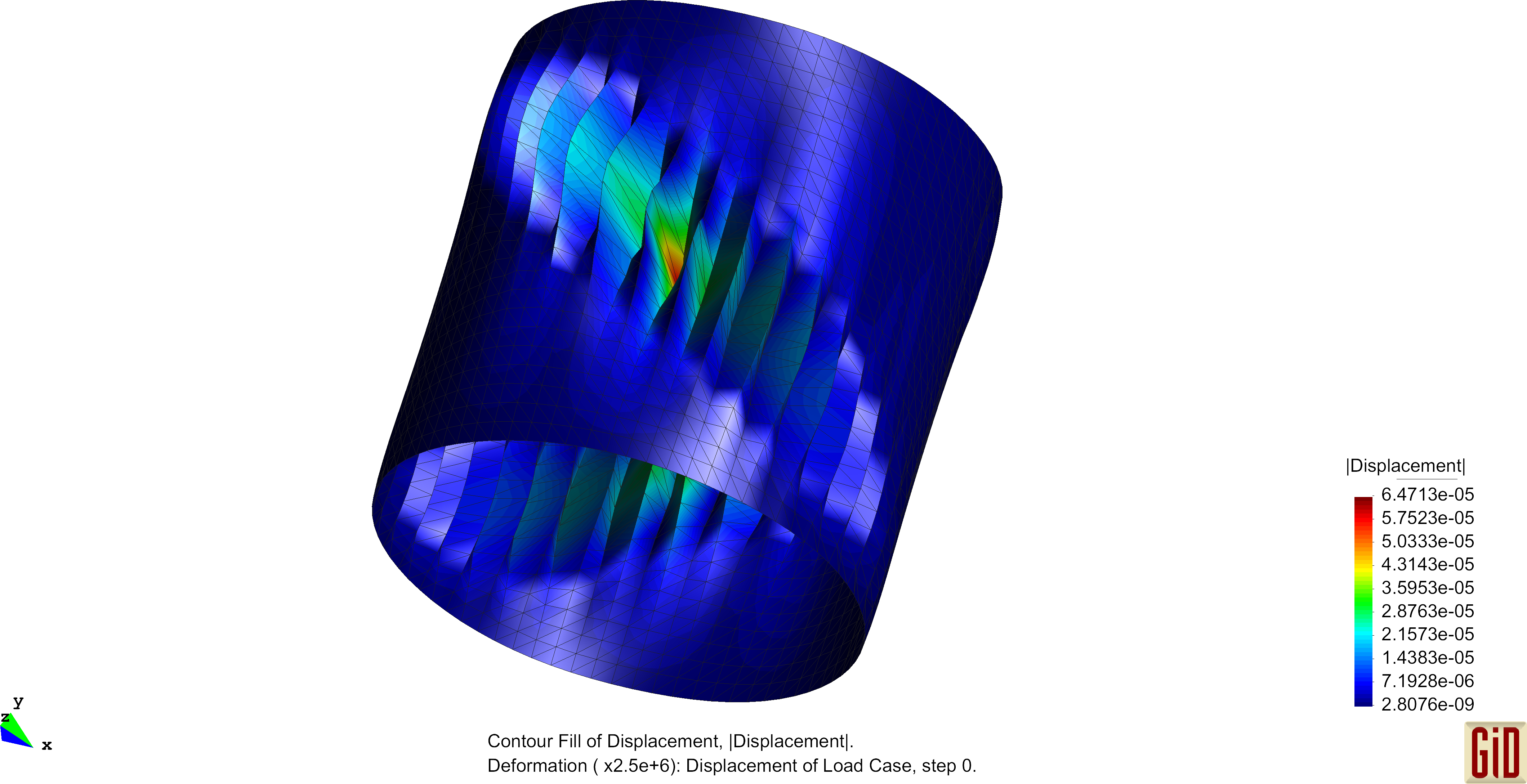
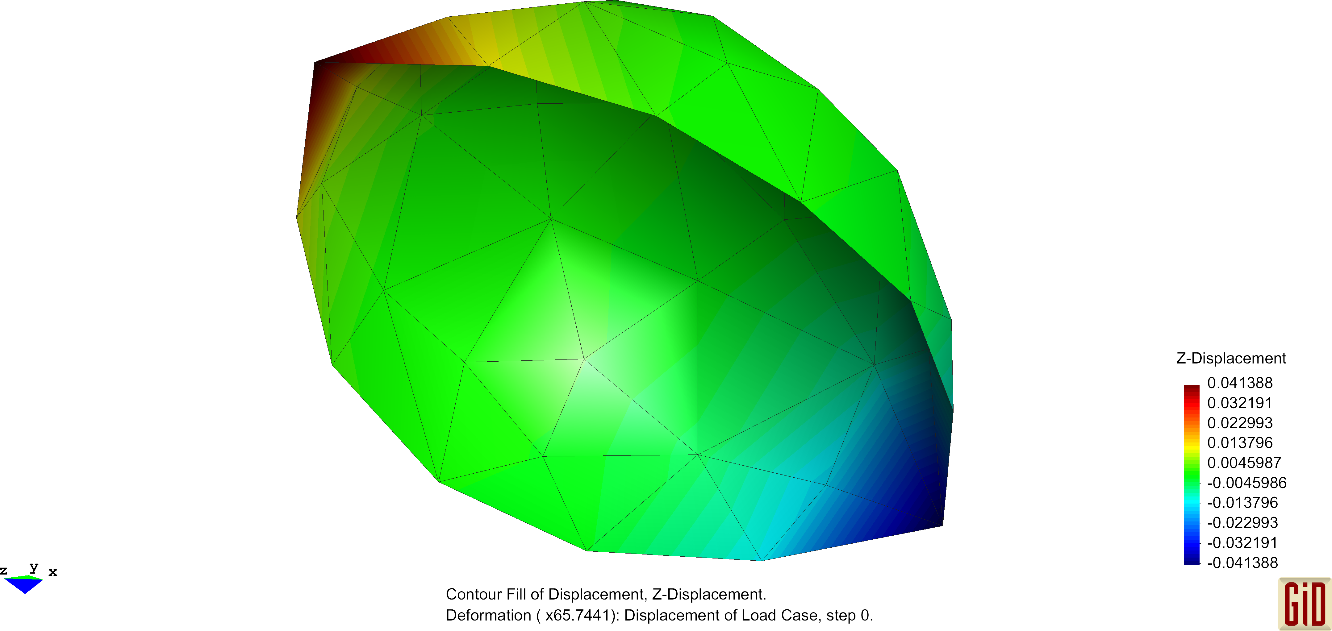
Due to the linear interpolation of the nodal directors, no change in the normal field will occur, hence no change of the curvature can be detected. This represents a deformation, which can not be captured by the formulas and therefore will not enter the bending part of the internal virtual work. One therefore speaks of a zero-energy deformation mode. Performing analysis with this operator will in some cases produce this "zig-zag"-like results and the use of this curvature operator is not recommended. Examples of these unphysical deformation figures are shown below.
CEG: curvature calculation through enhanced geometry
In order to overcome these spurious deformation modes a second approach is implemented. The basic idea of this method of curvature calculation is to enhance the geometry with an additional rotation field. The nodal director of the surface is in general inclined against the tangential plane of the specific isoparametric element, although it should be normal to it. In order to repair this discrepancy, additional rotations are introduced, which can be determined by the inclination of the nodal director against the tangential plane. These rotations are then interpolated using suitable shape functions. The enhanced curvature of a CEG element consists of the actual curvature of the isoparametric surface and the additional curvature obtained by the derivation of the introduced additional rotation field w.r.t the surface coordinates.
Modelling aspects
Clamped edges
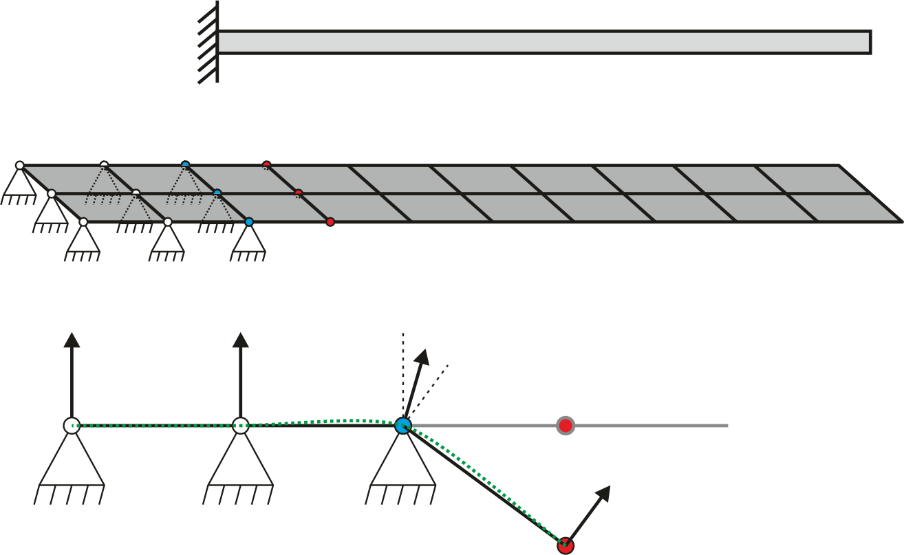
For the additional stiffness at the free degrees of freedom (red nodes) one additional fixed element row is sufficient. Only for curved geometries a second row is necessary in order to interpolate the curvature through the first fixed element row correctly. In the lower part of the figure the situation for the deformed geometry is depicted. The geometry approximated through the nodal directors is displayed with a green dotted line and one sees the deformation in the first fixed element row. One trick to influence the direction of the nodal director is to model the fixed element rows really small, since the area of the element enters the formula of the nodal director as a weighting factor. Therewith the unwanted deformation in the fixed element row becomes smaller.
Symmetry
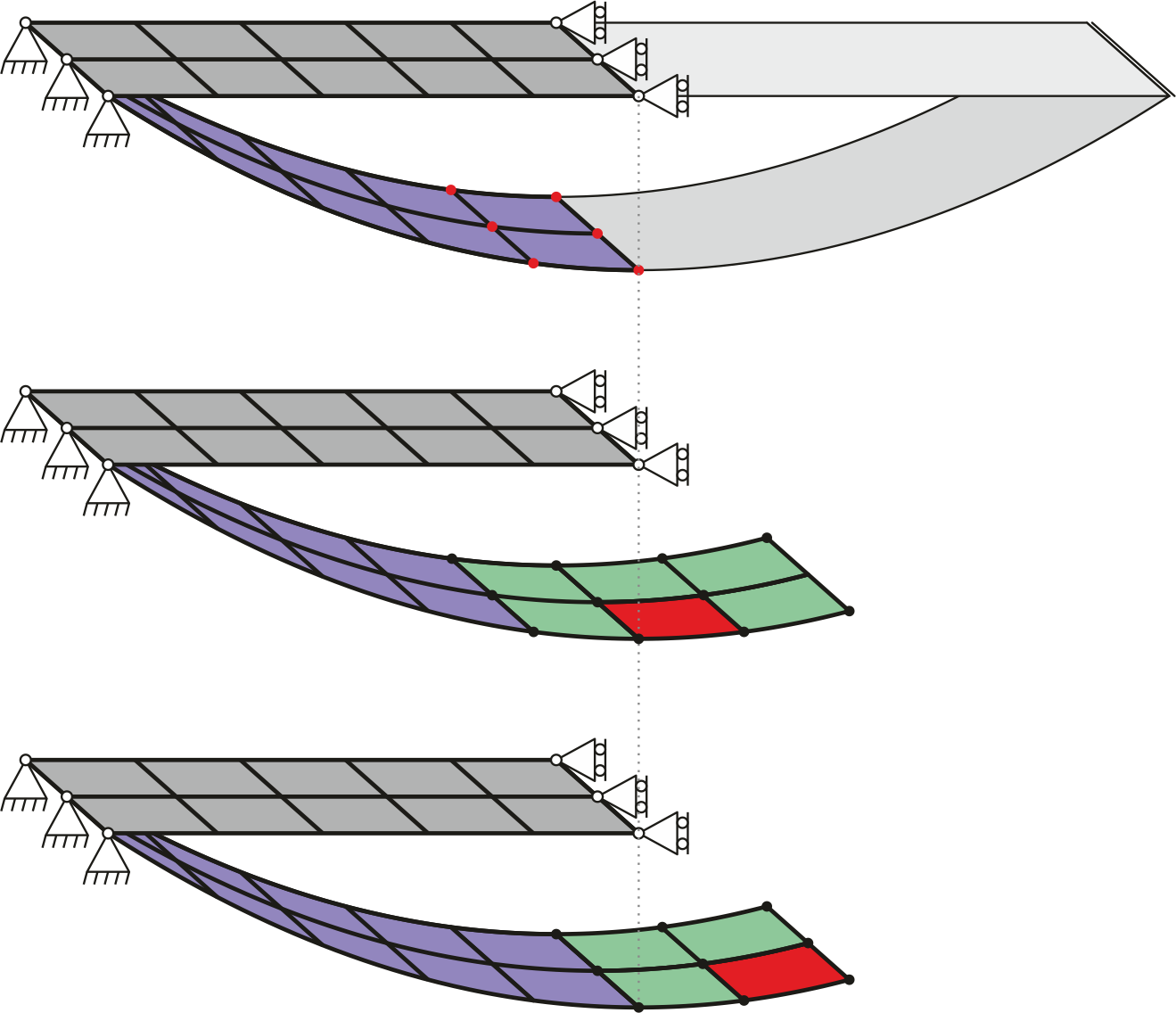
The appliciation of symmetry is not implemented for this element, because contributing elements behind the symmetry planes are missing. For a better understanding see in the above figure the rectangular sheet of metal subjected to selfweight, while both short ends are supported. Modelling only half it, the dark grey elements would result and the additional boundary condition is the rollersupport preventing the elements to deform above the symmetry plane. The first thing which is not possible is to keep the rotations at the symmetry plane fixed, therefore disconuities can evolve at the symmetry plane. The second thing are missing stiffness contributions, marked at the red dots in the first sketch. Elements located behind the symmetry plane adding their stiffness contributions are missing. In the second and third sketch these missing elements are drawn. Exemplarily Masterelements (red) with their neighboring patch/influence zone (green) are shown and one can clearly see how stiffness contributions are simply neglected.
Free edges
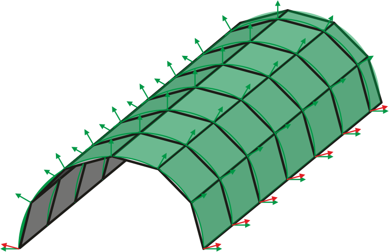
Free edges do not need special attention in the modelling, but an interesting aspect should be highlighted. For curved geometries the representation of curvature at free edges is not correct. Imagine half of a Cylinder as depicted in the above figure. The curvature on the continous surface (green) is everywhere the same. For the discretized geometry (grey) the nodal directors match the normal vectors of the surface, but not at the free edge. Due to missing information how the surface would continue a correct representation of the curvature is not possible. The nodal directors at the free edge (red) are simply normal to the element. This effect vanishes in the limit where the elementsize tends towards zero.
Tested examples
The following benchmarks show the good behaviour of the Shell10 element.
Shell Obstacle Course
The intention of the shell obstacle course by Belytschko et al. [3] is to test the ability of elements to handle inextensional bending modes of deformation, rigid-body motion without straining, and complex membrane states of stress. It consists of three problems, namely the Scordelis- Lo Roof, the pinched cylinder with diaphragm and the hemispherical shell.
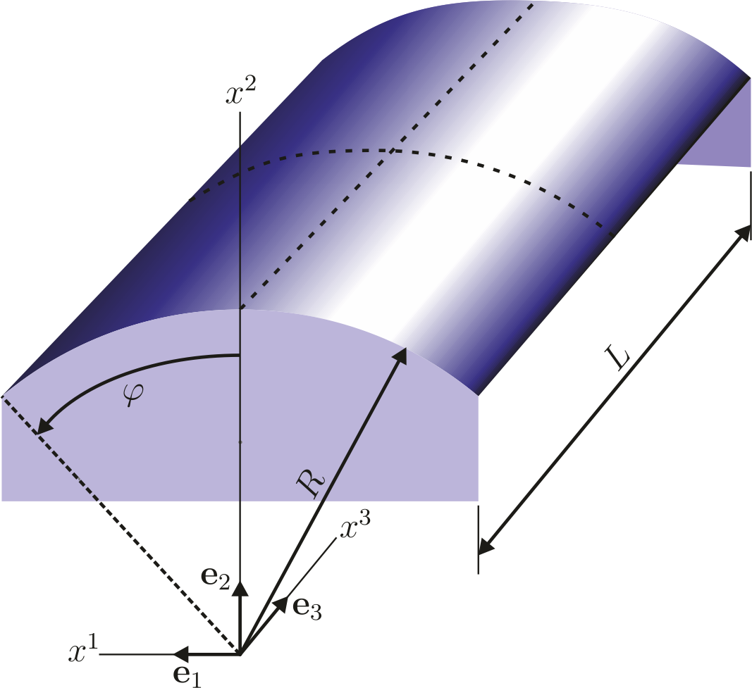
Scordelis-Lo Roof
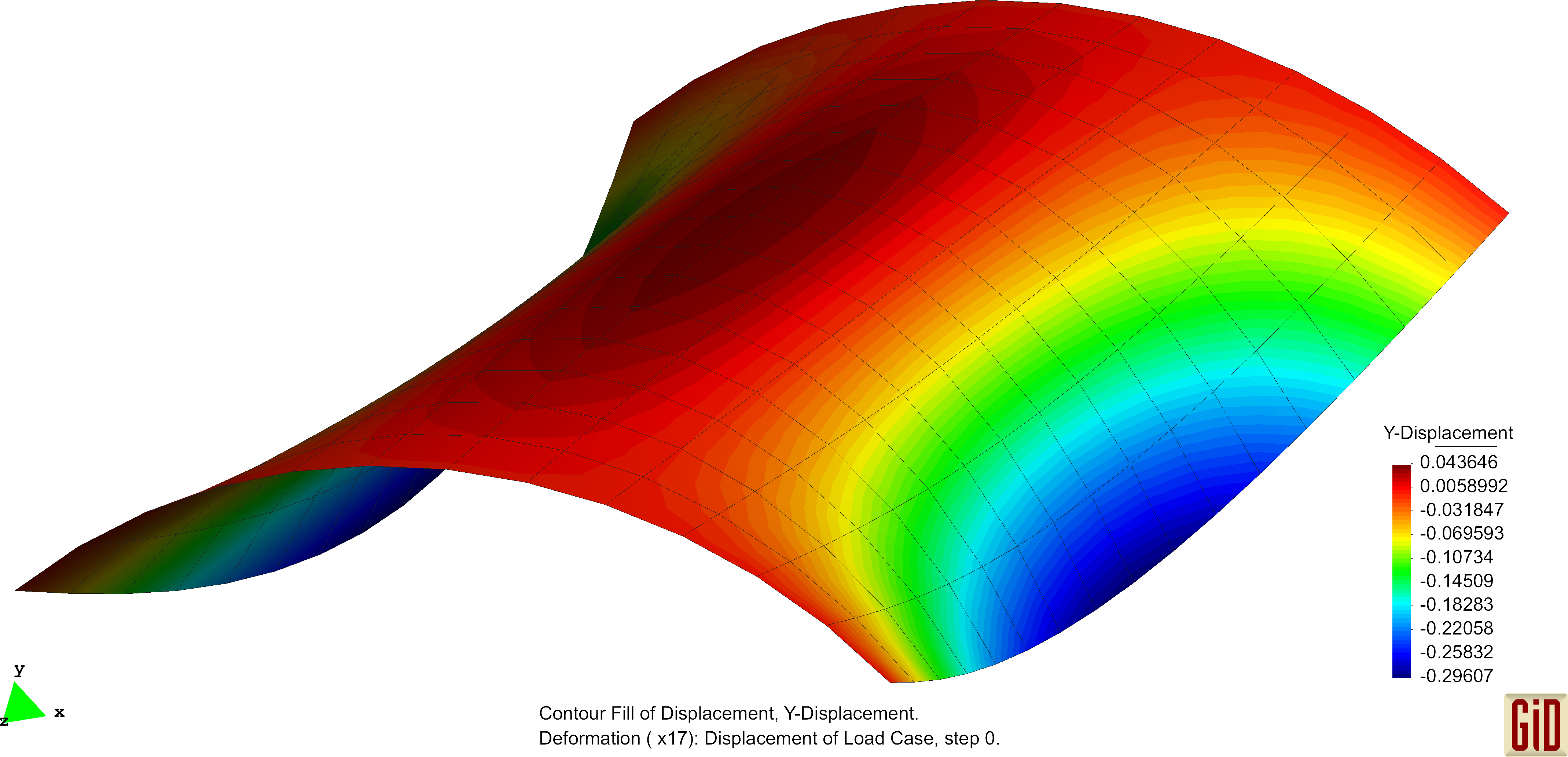
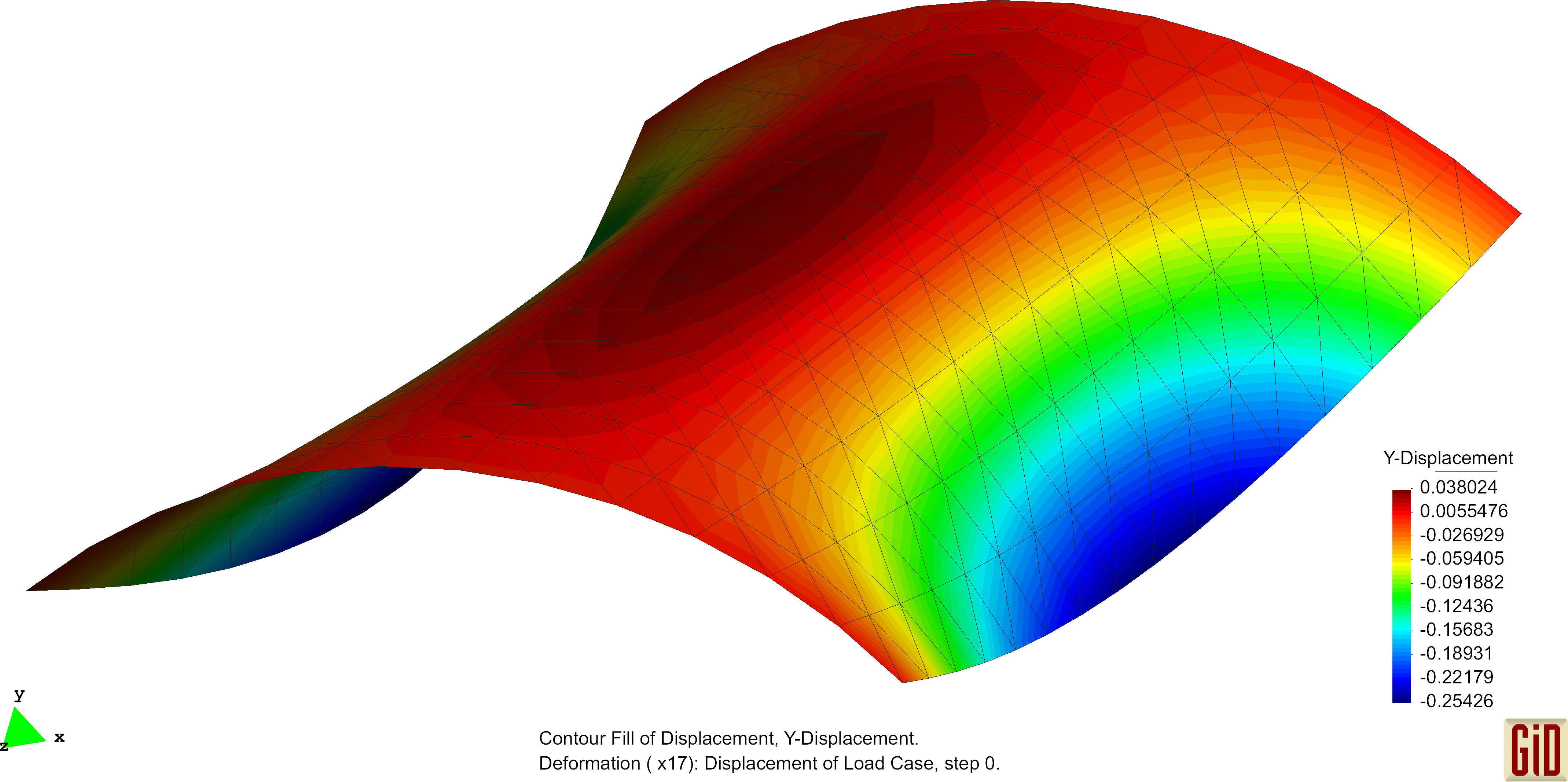
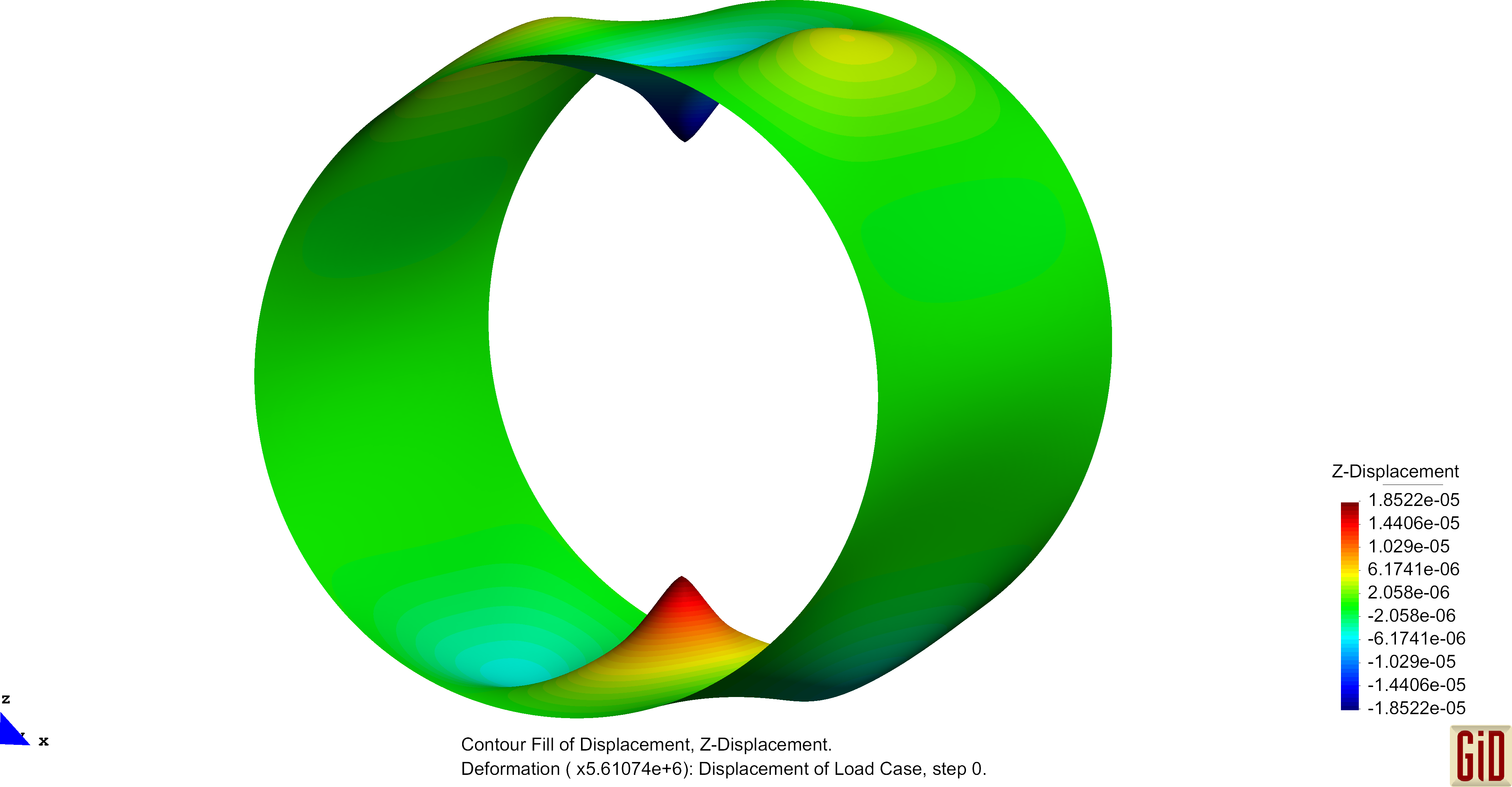
The Scordelis-Lo roof is a section of a cylindrical shell subjected to a uniform gravity load. Exemplarily deformation figures are shown below. The normalized convergence curve is shown here: File:Conv ScoLoRoof.pdf
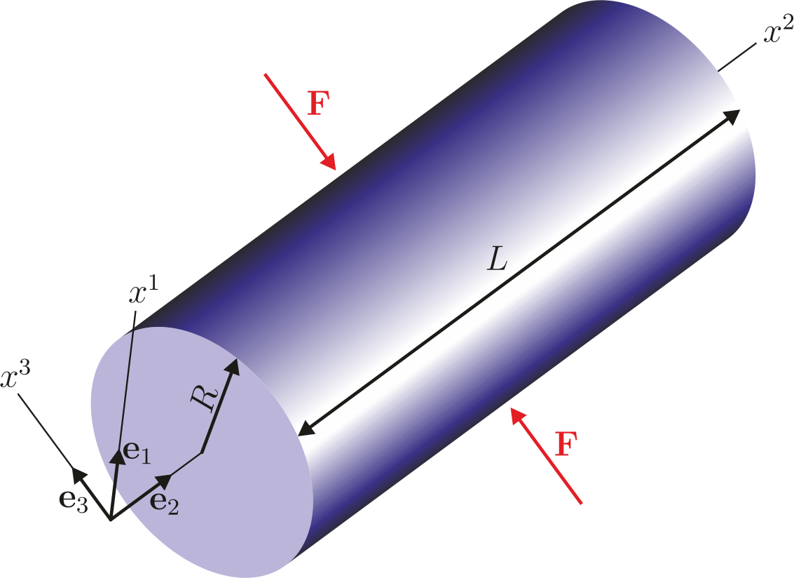
Pinched Cylinder
The pinched cylinder with diaphragms is a cylindrical shell subjected to two opposite point loads located in the middle of the cylinder. Exemplarily deformation figures are shown below. The normalized convergence curve is shown here: File:Conv PinchedCyl.pdf
The Pinched Cylinder with its regular mesh is prone to the previously mentioned zero-energy modes. Results of the unphysical deformation behaviour is shown below.
Hemispherical Shell
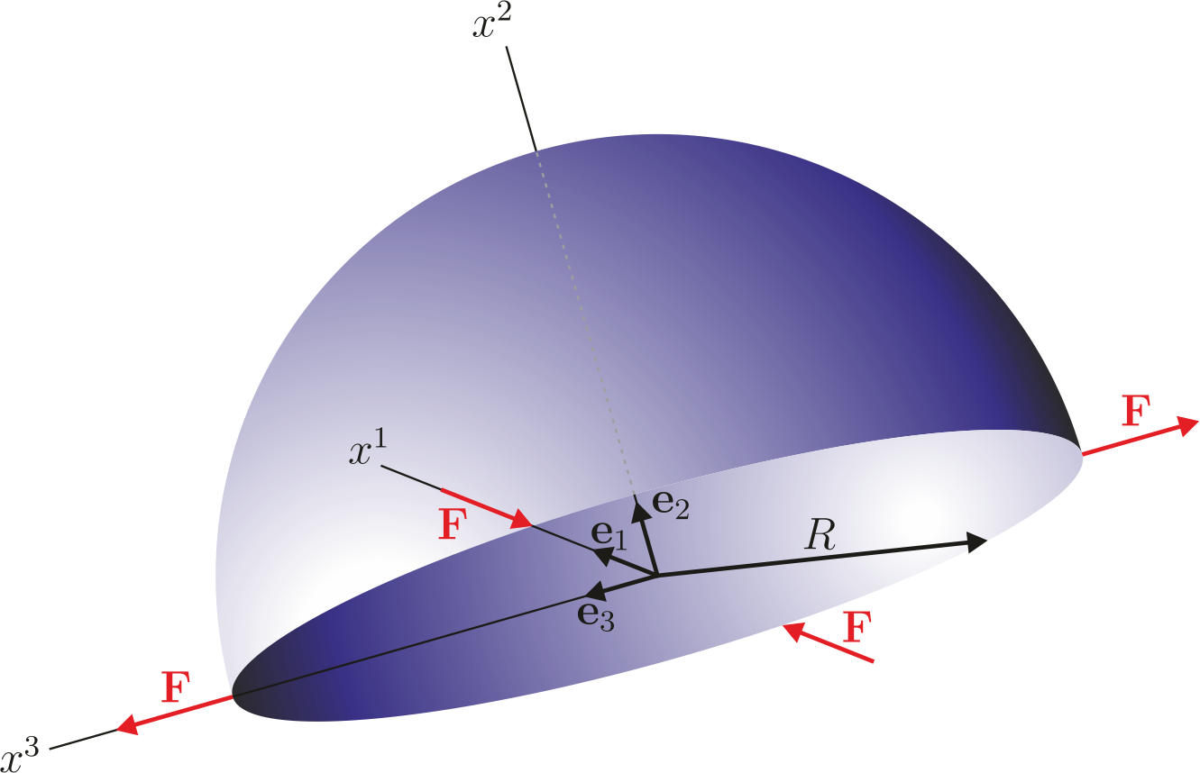
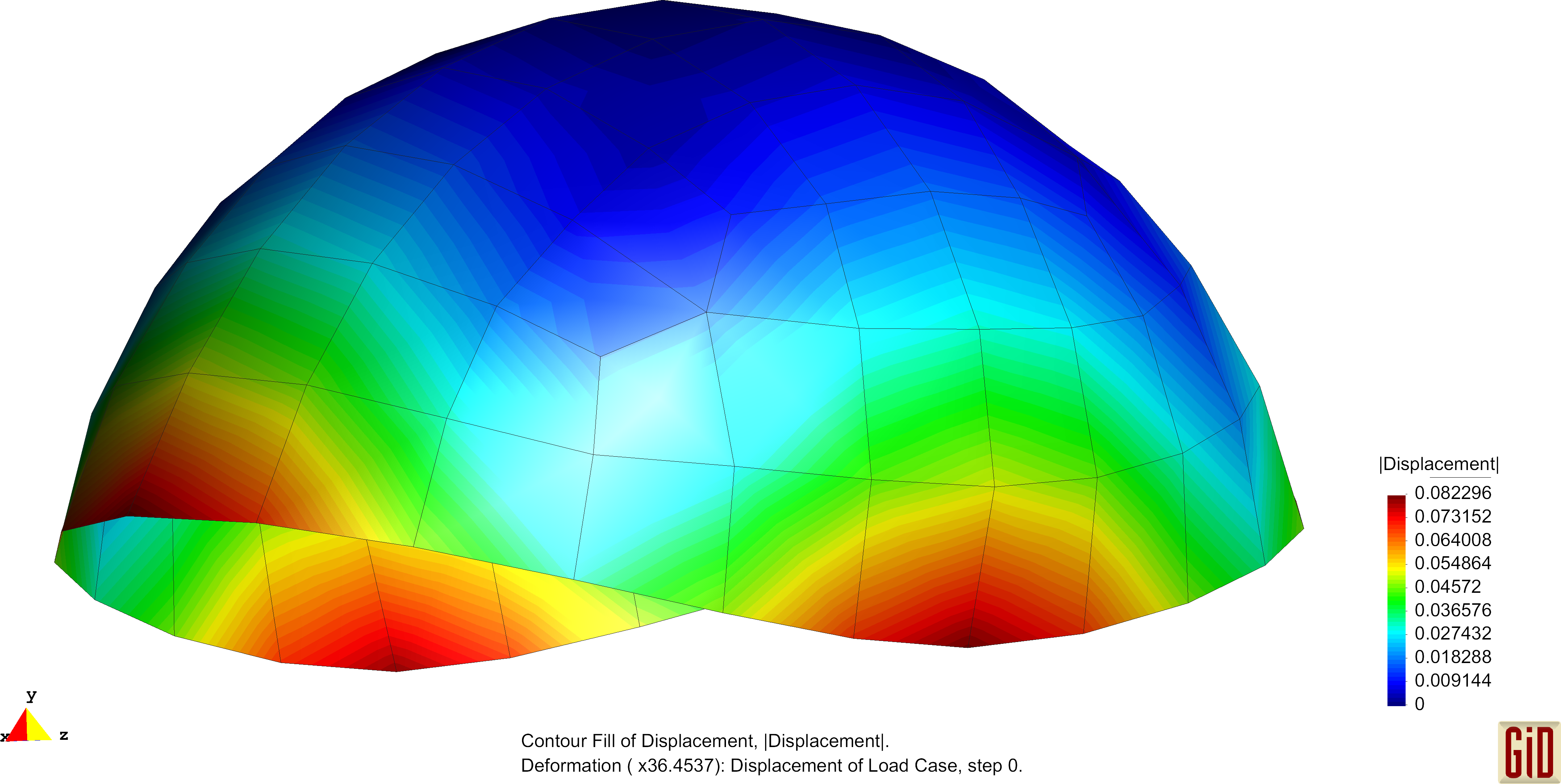
The hemisperical shell is subjected to four point loads acting every 90 degrees at the free bottom of the structure. Exemplarily deformation figures are shown below. The normalized convergence curve is shown here: File:Conv Hemishell.pdf
Benchmarks
The main benchmark files in the Carat++-repository are
'../examples/benchmark_examples/elements/shell10_quad_CEG/cbm_ScoLoRoof_full_quad_struc_192.dat'
'../examples/benchmark_examples/elements/shell10_quad_CIN/cbm_HemiShell_full_quad_103.dat'
'../examples/benchmark_examples/elements/shell10_tria_CEG/cbm_PinchedCyl_full_tria_240.dat'
'../examples/benchmark_examples/elements/shell10_tria_CIN/cbm_ScoLoRoof_full_tria_struc_384.dat'
'../examples/benchmark_examples/elements/shell10_tria_nonlin/cbm_NONLN_Cyl_tria_8x8.dat'
References
- ↑ Linhard, J.; Wüchner, R.; Bletzinger K.U.: "Upgrading" membranes to shells — The CEG rotation free shell element and its application in structural analysis, Finite Elements in Analysis and Design, Elsevier, volume 44, pages 63-74, 2007
- ↑ Both, T.: Formulation and object oriented implementation of a nonlinear rotation free Kirchhoff shell element, Masterthesis, Chair of structural analysis, Technische Universität München, 2010
- ↑ BELYTSCHKO T., Stolarski H., Liu W., Carpenter N. and Ong J.: Stress projection for membrane and shear locking in shell finite elements, Computer Methods in Applied Mechanics and Engineering, 51:221–258, 1985
| Whos here now: Members 0 Guests 0 Bots & Crawlers 1 |
