Users:General FEM Analysis/Elements Reference/Shell8
(Created page with 'Category: Users:General FEM == General Description == {| |Triangular Shell8 elements |[[File:Element_shell8_quadrilatera…') |
|||
| Line 29: | Line 29: | ||
| − | == | + | == Input Parameters == |
| + | |||
| + | === Parameter Description === | ||
{| border="1" cellpadding="3" cellspacing="0" | {| border="1" cellpadding="3" cellspacing="0" | ||
| Line 85: | Line 87: | ||
| − | Example of a | + | === Example of a Complete Input Block === |
<pre> | <pre> | ||
EL-PROP 1 : SHELL8 | EL-PROP 1 : SHELL8 | ||
Revision as of 07:57, 2 September 2010
Contents |
General Description
Element Type
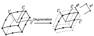
- This shell element is a "degenerated" shell element with 6 (external) degrees of freedom per node
- It is Reissner-Mindlin kinematics.
- It comprises enhancements according to the EAS method and the ANS method.
- It is able to consider a varying nodal thickness over the model.
Degrees of Freedom
The degrees of freedom are:
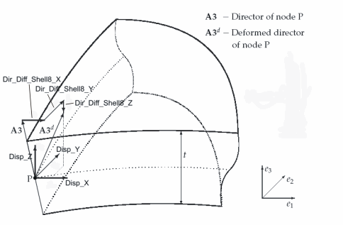
- the 3 translatoric components of the shell midplaine in the global cartesian frame (the 3 "classical" translatoric DOFs): They are named Disp_X, Disp_Y, Disp_Z.
- the three deformation components of the nodal director (See also figure on the right). They are named Dir_Diff_Shell8_X, Dir_Diff_Shell8_Y and Dir_Diff_Shell8_Z. This is a unique property of this element. Thus the element cannot be coupled with globally oriented rotatoric DOFs of other element types.
A seventh degree of freedom is added on the element level via the Enhanced Assumed Strain Method. That's why the element is called to be a "7 parameter formulation". However, this seventh nodal degree of freedom is condensed out on the element level and thus does not show up on the global level (No loads and no BCs can be applied on it).
Input Parameters
Parameter Description
| Compulsory Parameters | ||
| Parameter | Values, Default(*) | Description |
|---|---|---|
| MAT | EL-MAT int | Linking to a material input block |
| INT_TYPE_SHELL8 | FULL | Control of integration type |
| ANS | NONE, Q, T, QT, TQ | Assumed Natural Strains (ANS) method:
|
| EAS | M,B,T,Q,S | Enhances Assumed Strains (EAS) method
|
| FORCE | XYZ, RST_ORTHO, RST | Output control for stress constraints (This part is currently under development. Author: Michi, Matthias. Date: 08/2010.)
|
| SDC | real | condition factor for director length, recommended value: 1.0 |
| Optional Parameters | ||
| Parameter | Values, Default(*) | Description |
| THICKNESS | real | Element thickness. This parameter is not compulsory, as the thickness can also be described via nodal values. |
Example of a Complete Input Block
EL-PROP 1 : SHELL8
MAT=EL-MAT 1
THICKNESS=0.1
INT_TYPE_SHELL8 = FULL
SDC= 1.0
EAS = 4,4,4,0,4
ANS = Q
FORCE = RST_ORTHO
Element Loading
Pressure
Dead Load
Snow Load
Theory
The theory and finite element formulation is originally based on the work of Norbert Büchter [1], [2] [3]. Detailed investigations and additional remarks, especially in the context of a layer-wise formulation, can be found at [4] [5]. For the correct use of the Shell8 and the interpretation of related results, the following aspects should be considered:
Degrees of Freedom, Rotational DOFs, Moment Loads
The degrees of freedom consist of the three displacements of the midsurface (according to standard shell theory), and the three components of the deformation of the director (difference vector of director in actual geometry and director in reference geometry). Rotations are not used. This has to be taken into account at the formulation of BCs and Loads, especially at clamped supports and moment loads. Thus fixing the nodal DOF Dir_Diff_Shell8_X does not mean that the rotation around the x-axis is fixed, but it means that the x-component of the difference vector is zero. The same holds for the input of moment loads, which can be considered as a pair of forces in the respective direction. Moment loads are not implemented yet for the Shell8.
Deformation in Thickness Direction
The three components of the deformation of the director also comprise a possible deformation in thickness direction (change of thickness). The three DOFs Dir_Diff_Shell8_X, Dir_Diff_Shell8_Y and Dir_Diff_Shell8_Z could be converted in two rotations and one deformation in thickness direction. However, the thickness deformation does not necessarily coincide with the 6th degree of freedom (Dir_Diff_Shell8_Z)! This would only be true, if the shell midplaine would be parallel to the xy-plane. In general, the thickness deformation is that component of the difference vector, which is parallel to the director (i.e. a linear combination of all three cartesian components).
In case of a fixed support, also the thickness deformation is fixed. This is correct in the context of real physical clamped supports, but it is wrong in the context of clamped supports that model symmetry conditions.
EAS Enhancement, 7-parameter formulation
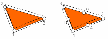
In case of a nonzero Poisson ratio, the 6 nodal DOFs are not sufficient in order to describe a shell theory which is assymptotically correct for bending situations. That's why a seventh parameter is introduced via the EAS method. The interpolation of this parameter within the element is described by value 3 of the parameter EAS of the property block. It has to be at least constant, i.e. the value must be at least =1. In general, for quadrilateral element a bilinear interpolation is recommended ( i.e. EAS = x,x,4,x,x), for triangular elements a constant or linear interpolation is suggested (see table above).
Element Technology
The are different kind of locking effects for shells. An overview is given at [5].
- (Bi-)linear elements (3 noded, 4-noded) are almost completely free of membrane locking, thus EAS is not really necessary here. For this reason, these elements are in the context of shells superior to elements of higher order. EAS does not completely eliminate membrane locking, but pushes it back to values of a higher critical parameter (higher slenderness)
- transverse shear locking must always be tackled, either by EAS or by ANS. Only in the context of extremely thick structures, this can be turned down
- Also thickness locking must always be tackled, either by EAS or by ANS.
- The in-plane bending behaviour of (bi-)linear elements is very bad. If such kind of deformations are expected to show up, then the use of EAS is recommended for the 4-noded element. However, this locking behaviour cannot be eliminated for the 3-noded triangular element. However, the related locking phenomena (in-plane shear locking, volumetric locking) are usually less critical for shells compared to the aforementioned ones.
Mesh Generation
As the DOF formulation is based on the difference vector, the physical meaning of the fourth up to sixth degree of freedom is dependent on the position and orientation of the director. Thus it has to be made sure that a director is uniquely defined at each node. Due to that it is important that the director is always pointing to one side of the shell surface.
References
- ↑ Büchter, N.: Zusammenführung von Degenerationskonzept und Schalentheorie bei endlichen Rotationen, Dissertation, Bericht Nr. 14, Institut für Baustatik, Universität Stuttgart, 1992
- ↑ Büchter, N., Ramm, E.: 3d-Extension of Nonlinear Shell Equations Based on the Enhanced Assumed Strain Concept, in: C. Hirsch, ed., Computational Methods in Applied Sciences, Elsevier, 39-59, 1992.
- ↑ Büchter, N., Ramm, E., Roehl, D., Three-Dimensional Extension of Nonlinear Shell Formulation Based on the Enhances Assumed Strain Concept, International Journal for Numerical Methods in Engineering, 37, 2551-2568, 1994.
- ↑ Braun, M., Nichtlineare Analysen von geschichteten, elastischen Flächentragwerken, Dissertation, Bericht Nr. 19, Institut für Baustatik, Universität Stuttgart, 1995.
- ↑ 5.0 5.1 Bischoff, M., Theorie und Numerik einer dreidimensionalen Schalenformulierung, Dissertation, Bericht Nr. 30, Institut für Baustatik, Universität Stuttgart, 1999.
| Whos here now: Members 0 Guests 0 Bots & Crawlers 1 |


