Users:General FEM Analysis/Materials Reference/Puck Failure Criterion
| (29 intermediate revisions by 2 users not shown) | |||
| Line 2: | Line 2: | ||
== General Description == | == General Description == | ||
| − | + | Puck Failure Criterion | |
| + | <ref> | ||
| + | A. Puck: Festigkeitsanalyse von Faser-Matrix-Laminaten. Hanser, 1996. ISBN 3-446-18194-6 | ||
| + | </ref> | ||
| + | <ref> | ||
| + | H. Deuschle. 3D failure analysis of UD fibre reinforced composites: Puck’s theory within FEA. | ||
| + | Phd thesis, Universität Stuttgart, 2010. | ||
| + | </ref> | ||
| + | <ref> | ||
| + | M. Knops. Analysis of Failure in Fiber Polymer Laminates. Springer Berlin Heidelberg, Berlin, | ||
| + | Heidelberg, 2008. | ||
| + | </ref> | ||
| + | is based on Mohr‘s fracture hypothesis | ||
| + | <ref> | ||
| + | O. Mohr. Welche Umstände bedingen die Elastizitätsgrenze und den Bruch eines Materials? | ||
| + | (German). Zeitschrift des Vereins deutscher Ingenieure, 24:1524 ff, 1900. | ||
| + | </ref> | ||
| + | which is appropriate for brittle fracture behaviour of composite materials. It can distinguish between fibre fracture and different inter-fibre fracture. Both 2D and 3D formulations are implemented into Carat++. | ||
Available fracture modes for 2D Puck Criterion are: | Available fracture modes for 2D Puck Criterion are: | ||
* Fibre Fracture (FF) | * Fibre Fracture (FF) | ||
| Line 11: | Line 28: | ||
* Fibre Fracture (FF) | * Fibre Fracture (FF) | ||
* Inter Fibre Fracture (IFF) | * Inter Fibre Fracture (IFF) | ||
| + | |||
| + | == Stresses on the Fracture Plane == | ||
| + | |||
| + | [[File:formel3.1.png|300px]] | ||
| + | |||
| + | [[File:formel3.2.png|150px]] | ||
| + | |||
| + | [[File:formel3.3_2.png|150px]] | ||
| + | |||
| + | [[File:Figure 3.4.png|500px]] | ||
| + | |||
| + | Stresses of the action plane | ||
| + | <ref> | ||
| + | M. Knops. Analysis of Failure in Fiber Polymer Laminates. Springer Berlin Heidelberg, Berlin, | ||
| + | Heidelberg, 2008. | ||
| + | </ref> | ||
| + | |||
| + | |||
| + | == Strength Analysis == | ||
| + | |||
| + | In order to judge if a stress vector on the stress spce is leading to damage, a mathematical expression is needed. | ||
| + | This expression is called ''fracture condition'' an is written as the following general form: | ||
| + | |||
| + | |||
| + | [[File:Formel3.4.png|150px]] | ||
| + | |||
| + | |||
| + | [[File:sigma_i.png|15px]] : Components of stress vector | ||
| + | |||
| + | R<sub>i</sub>. : Strengths under corresponding stresses | ||
| + | |||
| + | F : Fracture function | ||
| + | |||
| + | |||
| + | There are 6 main strengths that should be related to the occurring stress state: | ||
| + | |||
| + | [[File:6main_strengths.png|350px]] | ||
| + | |||
| + | The general form of fracture condition can also be rewritten as following: | ||
| + | |||
| + | [[File:Formel3.5.png|350px]] | ||
| + | |||
| + | F < 1 : no fracture | ||
| + | |||
| + | F = 1 : fracture limit reached and fracture occurs | ||
| + | |||
| + | F > 1 : fracture limit exceeded | ||
| + | |||
| + | with F [[File:Element.png|10px]] [0,[[File:unendlich.png|18px]]) | ||
| + | |||
| + | [[File:puck.png|1000px]] | ||
| + | <ref> | ||
| + | Altug Emiroglu, Master Thesis: Comparative Study of Puck and Tsai-Wu Failure Criteria, Technische Universität München, 2013. | ||
| + | </ref> | ||
| + | |||
| + | |||
| + | == Parameter Description == | ||
| + | |||
| + | {| border="1" cellpadding="3" cellspacing="0" | ||
| + | |colspan="3" style="background:#efefef;"| Compulsory Parameters | ||
| + | |- | ||
| + | !Parameter | ||
| + | !Values, Default(*) | ||
| + | !Description | ||
| + | |- | ||
| + | !EF | ||
| + | |real | ||
| + | |Elasticity modulus of the fibres | ||
| + | |- | ||
| + | !RTL | ||
| + | |real | ||
| + | |Resistance to longitudinal tension (Direction 1) | ||
| + | |- | ||
| + | !RCL | ||
| + | |real | ||
| + | |Resistance to longitudinal compression (Direction 1) | ||
| + | |- | ||
| + | !RTT | ||
| + | |real | ||
| + | |Resistance to transverse tension (Direction 2) | ||
| + | |- | ||
| + | !RCT | ||
| + | |real | ||
| + | |Resistance to transverse compression (Direction 2) | ||
| + | |- | ||
| + | !RSL | ||
| + | |real | ||
| + | |Resistance to longitudinal shear | ||
| + | |- | ||
| + | !VFF | ||
| + | |real | ||
| + | |Volume fraction of the fibres | ||
| + | |- | ||
| + | !PTTL | ||
| + | |real | ||
| + | |Inclination parameter,[[File:pt.png|25px]] | ||
| + | |- | ||
| + | !PCTL | ||
| + | |real | ||
| + | |Inclination parameter,[[File:pc.png|25px]] | ||
| + | |- | ||
| + | |||
| + | |colspan="3" style="background:#efefef;"| Optional Parameters | ||
| + | |- | ||
| + | !Parameter | ||
| + | !Values, Default(*) | ||
| + | !Description | ||
| + | |- | ||
| + | !STRESS TYPE | ||
| + | |2D, 3D | ||
| + | |Indicates what kind of stress state should be used to calculate the failure condition. When not given, related element’s stress type is taken. | ||
| + | |- | ||
| + | !NUE12F | ||
| + | |real | ||
| + | |Poisson’s ratio for fibres. (''De f ault'' = 0.2) | ||
| + | |- | ||
| + | !MGF | ||
| + | |real | ||
| + | |Amplification factor (''De f ault'' = 1.2) | ||
| + | |- | ||
| + | !S, M | ||
| + | |real | ||
| + | |Parameters necessary for calculation of weakening due to [[File:sigma.png|20px]] (''De f ault'' = S = M = 0.5) | ||
| + | |- | ||
| + | !PTT | ||
| + | |real | ||
| + | |Inclination parameter [[File:p.png|25px]]. When not given, calculated using the strength values. See Section 3.1.2.3 | ||
| + | |- | ||
| + | !WEAKENING | ||
| + | |int | ||
| + | |Switch for calculation of weakening due to [[File:sigma.png|20px]]. | ||
| + | * 0 = OFF | ||
| + | * 1* = ON | ||
| + | |- | ||
| + | !FPS | ||
| + | |SWS*, GSS | ||
| + | |Switch for fracture plane search algorithm. | ||
| + | * SWS* = Stepwise Search Algorithm | ||
| + | * GSS = Golden Section Search Algorithm | ||
| + | |- | ||
| + | !FPS_SWS_SIZE | ||
| + | |real | ||
| + | |Step size for step-wise fracture plane search | ||
| + | |- | ||
| + | |- | ||
| + | |} | ||
| + | |||
| + | |||
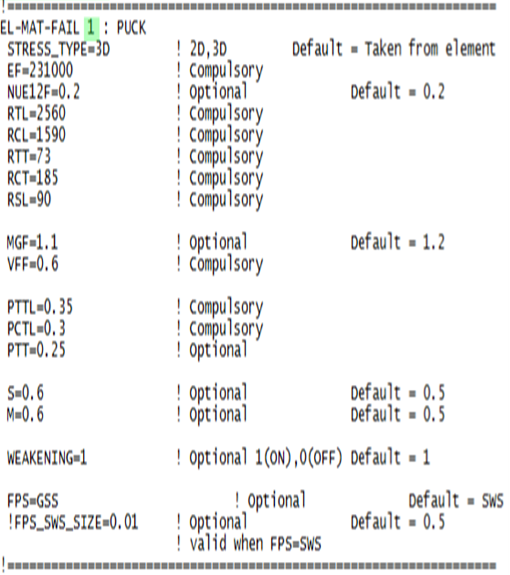
| + | === Example of a Complete Input Block === | ||
| + | [[File:input_puck.png|500px]] | ||
| + | |||
| + | |||
| + | == References == | ||
| + | <references/> | ||
Latest revision as of 10:05, 15 February 2013
Contents |
General Description
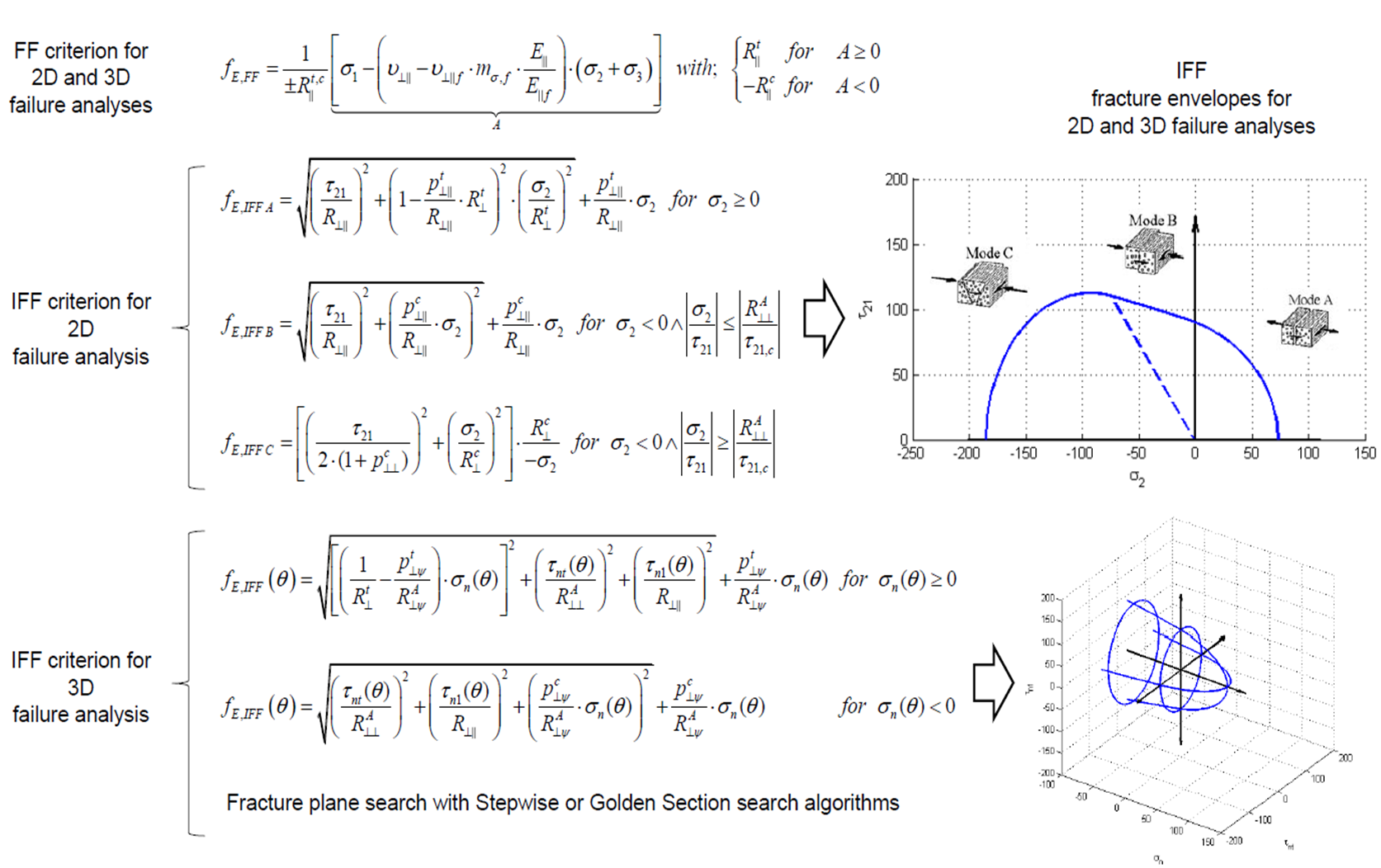
Puck Failure Criterion [1] [2] [3] is based on Mohr‘s fracture hypothesis [4] which is appropriate for brittle fracture behaviour of composite materials. It can distinguish between fibre fracture and different inter-fibre fracture. Both 2D and 3D formulations are implemented into Carat++. Available fracture modes for 2D Puck Criterion are:
- Fibre Fracture (FF)
- Inter Fibre Fracture Mode A (IFF A)
- Inter Fibre Fracture Mode B (IFF B)
- Inter Fibre Fracture Mode C (IFF C)
Available fracture modes for 3D Puck Criterion are:
- Fibre Fracture (FF)
- Inter Fibre Fracture (IFF)
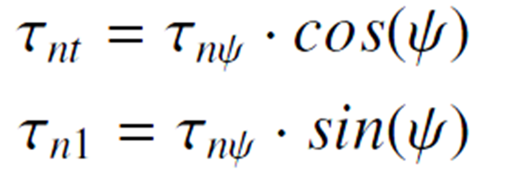
Stresses on the Fracture Plane
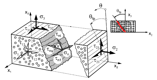
Stresses of the action plane [5]
Strength Analysis
In order to judge if a stress vector on the stress spce is leading to damage, a mathematical expression is needed. This expression is called fracture condition an is written as the following general form:
Ri. : Strengths under corresponding stresses
F : Fracture function
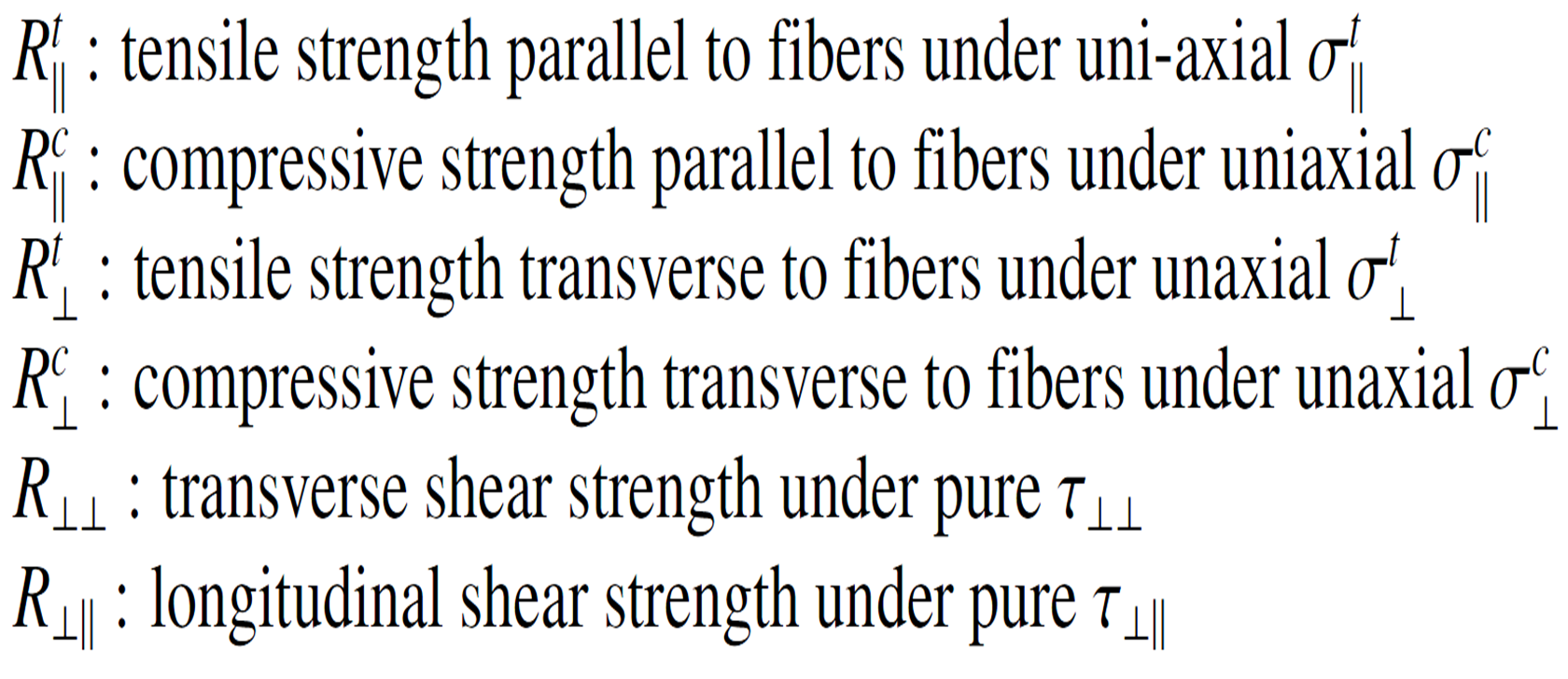
There are 6 main strengths that should be related to the occurring stress state:
The general form of fracture condition can also be rewritten as following:
F < 1 : no fracture
F = 1 : fracture limit reached and fracture occurs
F > 1 : fracture limit exceeded
Parameter Description
Example of a Complete Input Block
References
- ↑ A. Puck: Festigkeitsanalyse von Faser-Matrix-Laminaten. Hanser, 1996. ISBN 3-446-18194-6
- ↑ H. Deuschle. 3D failure analysis of UD fibre reinforced composites: Puck’s theory within FEA. Phd thesis, Universität Stuttgart, 2010.
- ↑ M. Knops. Analysis of Failure in Fiber Polymer Laminates. Springer Berlin Heidelberg, Berlin, Heidelberg, 2008.
- ↑ O. Mohr. Welche Umstände bedingen die Elastizitätsgrenze und den Bruch eines Materials? (German). Zeitschrift des Vereins deutscher Ingenieure, 24:1524 ff, 1900.
- ↑ M. Knops. Analysis of Failure in Fiber Polymer Laminates. Springer Berlin Heidelberg, Berlin, Heidelberg, 2008.
- ↑ Altug Emiroglu, Master Thesis: Comparative Study of Puck and Tsai-Wu Failure Criteria, Technische Universität München, 2013.
| Whos here now: Members 0 Guests 0 Bots & Crawlers 1 |

