Users:General FEM Analysis/Elements Reference/BeamNL
| (3 intermediate revisions by one user not shown) | |||
| Line 2: | Line 2: | ||
== General Description == | == General Description == | ||
| + | '''This element has never been finalized and is deprecated!''' | ||
| + | |||
=== Element Type === | === Element Type === | ||
| Line 19: | Line 21: | ||
** need for a neighbour-element search (inside one set of members, other elements have to be linked using [[Users:General FEM Analysis/BCs Reference/Dirichlet|''MPC-COUPLING'']]), | ** need for a neighbour-element search (inside one set of members, other elements have to be linked using [[Users:General FEM Analysis/BCs Reference/Dirichlet|''MPC-COUPLING'']]), | ||
** for the definition of kinks, two different sets of members have to be used (else kinks would be smoothed out), | ** for the definition of kinks, two different sets of members have to be used (else kinks would be smoothed out), | ||
| − | ** for starting members (i.e. with only 1 adjacent | + | ** for starting members (i.e. with only 1 adjacent element), the connection of node 1 to node 2 is the local x-axis. |
* the local y-axis ('''z'''<sub>loc</sub>) is defined with the help of an orientation point (''ORIENTATION_POINT_BEAMNL'', external to the beam element itself and common for one set of members; to be defined in the element property (see below)): an auxiliary vector ('''vec'''<sub>aux</sub>) pointing from node 1 to this external orientation point is set up. The local axis y is the result of the cross-product of this auxiliary vector and the local x-axis (mathematically spoken: '''y'''<sub>loc</sub> = '''vec'''<sub>aux</sub> x '''x'''<sub>loc</sub>). | * the local y-axis ('''z'''<sub>loc</sub>) is defined with the help of an orientation point (''ORIENTATION_POINT_BEAMNL'', external to the beam element itself and common for one set of members; to be defined in the element property (see below)): an auxiliary vector ('''vec'''<sub>aux</sub>) pointing from node 1 to this external orientation point is set up. The local axis y is the result of the cross-product of this auxiliary vector and the local x-axis (mathematically spoken: '''y'''<sub>loc</sub> = '''vec'''<sub>aux</sub> x '''x'''<sub>loc</sub>). | ||
* the local z-axis ('''z'''<sub>loc</sub>) is perpendicular to the other two local axes, following the right-hand-rule for x-y-z (i.e. once again using the cross-product). This makes z point in the half-space of the orientation point. | * the local z-axis ('''z'''<sub>loc</sub>) is perpendicular to the other two local axes, following the right-hand-rule for x-y-z (i.e. once again using the cross-product). This makes z point in the half-space of the orientation point. | ||
| Line 76: | Line 78: | ||
ORIENTATION_POINT_BEAMNL = 0.0, 10.0, 0.0 | ORIENTATION_POINT_BEAMNL = 0.0, 10.0, 0.0 | ||
</pre> | </pre> | ||
| − | |||
| − | |||
| − | |||
| − | |||
| − | |||
| − | |||
| − | |||
| − | |||
| − | |||
| − | |||
| − | |||
| − | |||
| − | |||
| − | |||
| − | |||
| − | |||
| Line 136: | Line 122: | ||
some papers of F. Gruttmann et al. | some papers of F. Gruttmann et al. | ||
| − | As it is based on linear ansatz-functions, the BeamNL-element needs | + | As it is based on linear ansatz-functions, the BeamNL-element needs sufficiently fine discretization in order to converge to the true solution. |
== References == | == References == | ||
<references/> | <references/> | ||
Latest revision as of 06:32, 13 January 2017
Contents |
General Description
This element has never been finalized and is deprecated!
Element Type
- This beam element is a 2 node non-linear 3D-beam for large rotations and small deformations (Green-Lagrange-strains) taking into account shear deformation (Timoshenko-beam element).
- This beam element has 6 DOFs per node (three translations and three rotations).
- The stiffness matrix is obtained using a one-point Gaussian quadrature, which results in an under-integration of the shear terms. This prevents shear-locking.
Degrees of Freedom
For the BeamNL element use the 3 translatoric degrees of freedom DISP_X, DISP_Y, DISP_Z and the 3 rotatoric degrees of freedom ROT_X, ROT_Y, ROT_Z.
Orientation of the local coordinate system
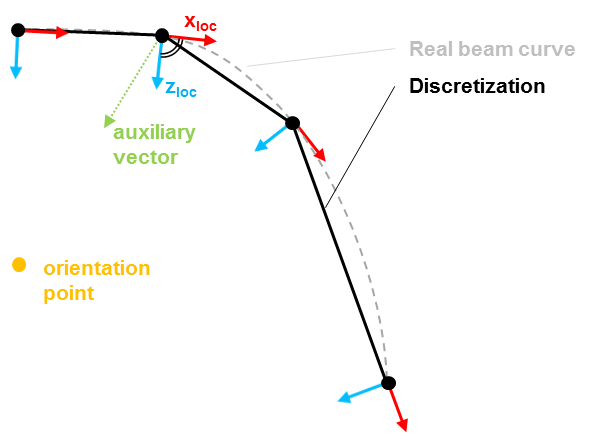
The BeamNL element uses the following definition for the determination of the local coordinate system in each node (needed for the orientation of I_22 and I_33,...), based on the idea of sets of members (dt.; Stabzug). These coordinate systems also have the role of a local Frenet-frame that is rotated with the element during a non-linear analysis. The difference between the current and the reference Frenet-frames is used to determine the curvatures of the element:
- the local x-axis (xloc) is defined as the tangent to the element in the considered point. This has important consequences:
- need for a neighbour-element search (inside one set of members, other elements have to be linked using MPC-COUPLING),
- for the definition of kinks, two different sets of members have to be used (else kinks would be smoothed out),
- for starting members (i.e. with only 1 adjacent element), the connection of node 1 to node 2 is the local x-axis.
- the local y-axis (zloc) is defined with the help of an orientation point (ORIENTATION_POINT_BEAMNL, external to the beam element itself and common for one set of members; to be defined in the element property (see below)): an auxiliary vector (vecaux) pointing from node 1 to this external orientation point is set up. The local axis y is the result of the cross-product of this auxiliary vector and the local x-axis (mathematically spoken: yloc = vecaux x xloc).
- the local z-axis (zloc) is perpendicular to the other two local axes, following the right-hand-rule for x-y-z (i.e. once again using the cross-product). This makes z point in the half-space of the orientation point.
- addition: If the local x-axes at both ends (i.e. nodes) of the element don't point in the same direction (due to the situation of the orientation point), the x-axis at the second node is switched by 180 degrees.
Input Parameters
Parameter Description
| Compulsory Parameters | ||
| Parameter | Values, Default(*) | Description |
|---|---|---|
| MAT | EL-MAT int | Number for the used Material
e.g. MAT=EL-MAT 1 |
| AREA | Definition of the cross-sectional area of the beam | |
| SHEAR_SECTION_Y, SHEAR_SECTION_Z | Definition of the shear-cross-sectional area of the beam in y- and z-direction | |
| I_22, I_33 | Definition of the moments of inertia around the local y- and z-axis | |
| I_23 | Definition of the mixed moment of inertia | |
| I_T | Definition of the torsional resistance I_T | |
| ORIENTATION_POINT_BEAMNL | External orientation point for the set of beam members. | |
Example of a Complete Input Block
EL-PROP 1 : BEAMNL
MAT= EL-MAT 1
AREA=0.015  SHEAR_SECTION_Y = 0.0075   SHEAR_SECTION_Z = 0.015
I_22=1.125  I_33=0.03125
I_23=1.23 I_T=1.15625
ORIENTATION_POINT_BEAMNL = 0.0, 10.0, 0.0
Use of the shear sections SHEAR_SECTION_Y and SHEAR_SECTION_Z
The shear sections SHEAR_SECTION_Y and SHEAR_SECTION_Z depend on the cross section of the beam and can be obtained by multiplying the area of the beam AREA with the shear correction factor α which is dependent on the shape of the sections. For a rectangle, α=5/6.
Use of the rotation parameter THETA
The rotation parameter THETA and its use is explained in the section concerning the coordinate system above.
The mixed moment of inertia I_23
The mixed moment of inertia I_23 is equal to 0 if one of the two local axes y and z is an axis of symmetry of the section.
The external point of orientation ORIENTATION_POINT_BEAMNL
The external point of orientation ORIENTATION_POINT_BEAMNL has to be entered with its coordinates in the global XYZ-frame in order to define the orientation of the local coordinate system of the beam.
Element Loading
For the moment, only nodal forces in the three global directions can be applied (i.e. Fx, Fy, Fz).
Pressure
- not defined yet
Dead Load
- not defined yet
Snow Load
- not defined yet
Tests and Benchmarks
Static linear analysis
For the moment, the element BeamNL has successfully been tested in 3D in all its linear static features, including
- bending, axial deformation, torsion,
- shear deformation (separately definable for both local axes),
- rotation around the local axis.
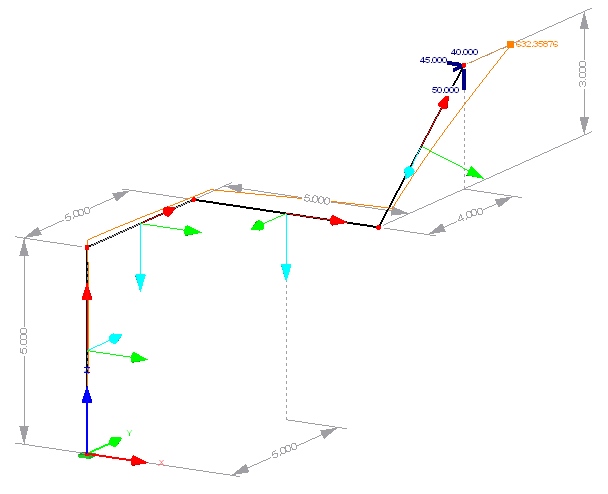
As an example, the structure on the right was part of the final tests.
Theory
The element implementation mainly follows the implementation of a non-linear 3D-beam element in the PhD-thesis of Roland Sauer [1], and some papers of F. Gruttmann et al.
As it is based on linear ansatz-functions, the BeamNL-element needs sufficiently fine discretization in order to converge to the true solution.
References
- ↑ Sauer, R.: Eine einheitliche Finite-Element-Formulierung für Stab- und Schalentragwerke mit endlichen Rotationen, Institut für Baustatik, Universität Karlsruhe, 1998
| Whos here now: Members 0 Guests 0 Bots & Crawlers 1 |

