Users:General FEM Analysis/Elements Reference/Beam1
(→Benchmark examples) |
(→General Description) |
||
| (6 intermediate revisions by one user not shown) | |||
| Line 16: | Line 16: | ||
If Theory of 2nd Order should be taken into account, a nonlinear calculation (ANALYSIS STA_GEO_NLIN) with only one timestep has to be executed. The stiffness matrix is calculated with the accurate auxiliary values (“Strichwerte”) A’, B’ and D’ see <ref name="Statik Ergänzung - Skript"> Bletzinger, K.-U.: Statik Ergänzung - Skript </ref>. In case of nonlinear calculation the shear correction factors are no longer considered. | If Theory of 2nd Order should be taken into account, a nonlinear calculation (ANALYSIS STA_GEO_NLIN) with only one timestep has to be executed. The stiffness matrix is calculated with the accurate auxiliary values (“Strichwerte”) A’, B’ and D’ see <ref name="Statik Ergänzung - Skript"> Bletzinger, K.-U.: Statik Ergänzung - Skript </ref>. In case of nonlinear calculation the shear correction factors are no longer considered. | ||
| + | |||
| + | === Dynamic === | ||
| + | |||
| + | Since a mass-matrix is implemented, the Beam1-element can also be used in dynamic analyses (including eigenfrequency,...) where it has already been successfully applied. | ||
=== Orientation of the local coordinate system === | === Orientation of the local coordinate system === | ||
| Line 88: | Line 92: | ||
== Element Loading == | == Element Loading == | ||
For the moment, only nodal forces in the three global directions can be applied (i.e. ''Fx, Fy, Fz''). | For the moment, only nodal forces in the three global directions can be applied (i.e. ''Fx, Fy, Fz''). | ||
| − | + | Being a line element not all general load cases are applicable. | |
| − | + | ||
| − | + | ||
=== Dead Load === | === Dead Load === | ||
| − | * implemented | + | * implemented |
| − | + | ||
| − | + | ||
| − | + | ||
== Tests and Benchmarks == | == Tests and Benchmarks == | ||
| Line 116: | Line 115: | ||
* buckling analysis of a single-span column (Euler 2): ..\examples\benchmark_examples\elements\beam1\cbm_beam1_buckling.dat | * buckling analysis of a single-span column (Euler 2): ..\examples\benchmark_examples\elements\beam1\cbm_beam1_buckling.dat | ||
* using the ElementBeam1 as a design element starting with a quarter-circle: ..\examples\benchmark_examples\elements\beam1\cbm_beam1_design.dat | * using the ElementBeam1 as a design element starting with a quarter-circle: ..\examples\benchmark_examples\elements\beam1\cbm_beam1_design.dat | ||
| + | * Theory of 2nd order under tension and compression: ..\examples\benchmark_examples\elements\beam_thII\cbm_Beam1_Th2O_1_Bsp_Skript_2.dat | ||
* spatial frame including local orientations THETA (see depicted above) in a linear computation under dead load: ..\examples\benchmark_examples\elements\beam1\cbm_beam1_stalin_deadload.dat | * spatial frame including local orientations THETA (see depicted above) in a linear computation under dead load: ..\examples\benchmark_examples\elements\beam1\cbm_beam1_stalin_deadload.dat | ||
| Line 125: | Line 125: | ||
Wunderlich <ref name="Wunderlich">Wunderlich, W.: Statik der Stabtragwerke, Teubner, 2004</ref>. | Wunderlich <ref name="Wunderlich">Wunderlich, W.: Statik der Stabtragwerke, Teubner, 2004</ref>. | ||
| − | As it is based on the Hermite-form functions, a Bernoulli beam can be modelled by one single element. | + | As it is based on the Hermite-form functions (for the linear element), a Bernoulli beam can be modelled by one single element. |
| + | |||
| + | Theory of 2nd order has been implemented according to <ref name="Mehlhorn">von Mehlhorn, G.: Ingenieurbau - Grundwissen: Baustatik / Baudynamik, Ernst&Sohn, 1995</ref>, pp. 179/180. | ||
== References == | == References == | ||
<references/> | <references/> | ||
Latest revision as of 07:41, 13 January 2017
Contents |
General Description
Element Type
- This beam element is a 2 node linear 3D-beam taking into account shear deformation (Timoshenko-beam element). For non-linear analyses the element is enriched by theory of 2nd order kinematics.
- This beam element has 6 DOFs per node (three translations and three rotations).
- The stiffness matrix for the linear calculation is hard-coded, thus not needing any integration. For theory of 2nd order, the normal force in the element leads to modifications in the stiffness matrix.
Degrees of Freedom
For the Beam1 element use the 3 translatoric degrees of freedom DISP_X, DISP_Y, DISP_Z and the 3 rotatoric degrees of freedom ROT_X, ROT_Y, ROT_Z.
Theory of 2nd Order
If Theory of 2nd Order should be taken into account, a nonlinear calculation (ANALYSIS STA_GEO_NLIN) with only one timestep has to be executed. The stiffness matrix is calculated with the accurate auxiliary values (“Strichwerte”) A’, B’ and D’ see [1]. In case of nonlinear calculation the shear correction factors are no longer considered.
Dynamic
Since a mass-matrix is implemented, the Beam1-element can also be used in dynamic analyses (including eigenfrequency,...) where it has already been successfully applied.
Orientation of the local coordinate system
The Beam1 element uses the following definition for the determination of the local coordinate system (needed for the orientation of IYY and IZZ,...):
- the local x-axis is oriented from node 1 to node 2 of the beam
- the local y-axis lies in the global XY-plane, such that the local z-axis points in the same half-space as the global Z-axis (mathematically spoken: the local z-axis and the global Z-axis result in a positive dot-product)
- the local z-axis is perpendicular to the other two local axis, following the right-hand-rule for x-y-z
- exception: If the local x-axis (i.e. the beam axis) points in the direction of global Z, the local y-axis points in the direction of the global Y-axis. The local z-axis once again follows the right-hand-rule for x-y-z.
In case that a rotation of the local coordinate system is needed (rotated elements, inverse definition of IYY and IZZ,...) an angle THETA has to be specified. This angle rotates the whole coordinate system around the local x-axis, following the right-thumb rule (i.e. the thumb of the right hand points in the direction of the local x-axis).
Orientation of the resultant forces
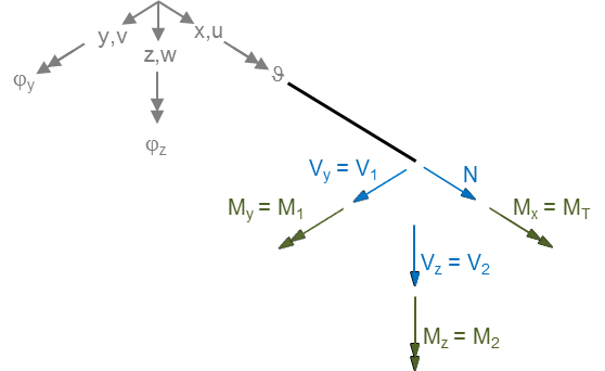
The Beam1 element has 6 resultant forces in accordance with the degrees of freedom. The resultant forces, [ N V1 V2 | MT M1 M2 ], are oriented along the local axes on the positive section of the beam. Note that the resultant forces are evaluated in the center of the beam element, so it's the mean value of the two ends. For the orientation, cf. also the orientation sketch:
Input Parameters
Parameter Description
| Compulsory Parameters | ||
| Parameter | Values, Default(*) | Description |
|---|---|---|
| MAT | EL-MAT int | Number for the used Material
e.g. MAT=EL-MAT 1 |
| AREA | Definition of the cross-sectional area of the beam | |
| IYY, IZZ | Definition of the moments of inertia | |
| Optional Parameters | ||
| KY, KZ | 0 | Shear correction factor; if 0 or no value specified, shear is not taken into account (Bernouolli-beam theory); Note: For Theory of 2nd Order, Bernoulli-beam theory is assumed. |
| THETA | 0 | Angle of rotation of the local coordinate system around the beam axis in degrees |
Example of a Complete Input Block
EL-PROP 1 : BEAM1
MAT= EL-MAT 1
AREA=5.555  IYY=1.222  IZZ=1.333
KY=1.4   KZ=1.5
THETA=90
Use of the shear correction factors KY and KZ
The shear correction factors KY and KZ depend on the cross section of the beam. For a rectangle, KY resp. KZ are usually considered equal to 1.2, which gives a factor of α=1/Ki=5/6.
Use of the rotation parameter THETA
The rotation parameter THETA and its use is explained in the section concerning the coordinate system above.
The torsional resistance IT
The torsional resistance IT is interpreted as the polar moment Ipp, i.e.: IT = Ipp = IYY + IZZ.
Element Loading
For the moment, only nodal forces in the three global directions can be applied (i.e. Fx, Fy, Fz). Being a line element not all general load cases are applicable.
Dead Load
- implemented
Tests and Benchmarks
Static linear analysis
For the moment, the element Beam1 has successfully been tested in 3D in all its linear static features, including
- bending, axial deformation, torsion,
- shear deformation (separately definable for both local axes),
- rotation around the local axis.
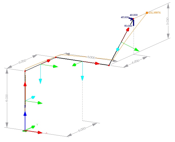
As an example, the structure on the right was part of the final tests.
Theory of 2nd order
Test herefore is a clamped frame with one pillar under compression and the other under tension cp. "Statik Ergänzung - Skript" [1]
Benchmark examples
- simple cantilever under tip-load (moment and force) in a linear calculation including shear deformation: ..\examples\benchmark_examples\elements\beam1\cbm_beam1.dat
- cantilever under various end-loads including shear deformation in a linear calculation: ..\examples\benchmark_examples\elements\beam1\cbm_beam1_stalin_timoshenko.dat
- buckling analysis of a single-span column (Euler 2): ..\examples\benchmark_examples\elements\beam1\cbm_beam1_buckling.dat
- using the ElementBeam1 as a design element starting with a quarter-circle: ..\examples\benchmark_examples\elements\beam1\cbm_beam1_design.dat
- Theory of 2nd order under tension and compression: ..\examples\benchmark_examples\elements\beam_thII\cbm_Beam1_Th2O_1_Bsp_Skript_2.dat
- spatial frame including local orientations THETA (see depicted above) in a linear computation under dead load: ..\examples\benchmark_examples\elements\beam1\cbm_beam1_stalin_deadload.dat
Theory
The element implementation mainly follows the implementation of a linear 3D-beam element in FELyX [2], Schwarz [3] and Wunderlich [4].
As it is based on the Hermite-form functions (for the linear element), a Bernoulli beam can be modelled by one single element.
Theory of 2nd order has been implemented according to [5], pp. 179/180.
References
- ↑ 1.0 1.1 Bletzinger, K.-U.: Statik Ergänzung - Skript
- ↑ https://www.rdb.ethz.ch/projects/project.php?proj_id=8314
- ↑ Schwarz, H.: Methode der Finiten Elemente, Teubner, 1991
- ↑ Wunderlich, W.: Statik der Stabtragwerke, Teubner, 2004
- ↑ von Mehlhorn, G.: Ingenieurbau - Grundwissen: Baustatik / Baudynamik, Ernst&Sohn, 1995
| Whos here now: Members 0 Guests 0 Bots & Crawlers 1 |

