Users:General FEM Analysis/Analyses Reference/Geodesic Lines
(→Example) |
(→Example) |
||
| (7 intermediate revisions by one user not shown) | |||
| Line 3: | Line 3: | ||
== General Description == | == General Description == | ||
| − | Geodesic line generation determines geodesic lines on a surface between two given nodes/points. | + | Geodesic line generation determines geodesic lines on a surface between two given nodes/points. A cable with a very high prestress is intorduced between the two endpoints. The out-of-plane forces are supressed as well as the forces at the two ends of the cable. Thus the cable finds the shortest distance in the membrane surface without altering it. By supressing the end-forces, the edge cables are not affected. <ref name="Dieringer"> Dieringer, F.: Numerical Methods for the Design and Analysis of Tensile Structures, Dissertation Lehrstuhl für Statik, 2014 </ref> |
| − | + | ||
| − | + | ||
| − | + | ||
| − | + | ||
| − | A | + | |
| − | + | ||
| − | + | ||
== Input Parameters == | == Input Parameters == | ||
| Line 86: | Line 79: | ||
NUMGEO 1 NODE_I=293 NODE_J=732 | NUMGEO 1 NODE_I=293 NODE_J=732 | ||
NUMGEO 2 NODE_I=89 NODE_J=797 | NUMGEO 2 NODE_I=89 NODE_J=797 | ||
| + | NUMGEO 3 NODE_I=1 NODE_J=841 | ||
| + | NUMGEO 4 NODE_I=88 NODE_J=796 | ||
| + | NUMGEO 5 NODE_I=294 NODE_J=733 | ||
</pre> | </pre> | ||
== Example == | == Example == | ||
| − | The following simple example shows the | + | The following simple example shows the geodesic line generation for a four-point sail, separating the geometry in 6 parts (depicted by the differently coloured stripes). The separation into parts is done automatically. In a following step, these parts can be used for the [[Users:General_FEM_Analysis/Analyses_Reference/Cutting_Pattern|cutting pattern generation]] |
{| | {| | ||
|[[File:Geodesic_lines.png]] | |[[File:Geodesic_lines.png]] | ||
|} | |} | ||
| − | The | + | The formfound geometry with its separation into the different parts is shown in the picture below. |
{| | {| | ||
|[[File:Geodesic_lines_formfound.png]] | |[[File:Geodesic_lines_formfound.png]] | ||
|} | |} | ||
| − | + | == Benchmark Examples == | |
| + | * Four point sail with three geodesic lines (not included in benchmarks due to amount of time but working!) ...benchmark_examples\analyses\geodesic_membrane1_I\x_cbm_4_point_geodesic.txt | ||
== References == | == References == | ||
<references/> | <references/> | ||
Latest revision as of 13:15, 9 December 2016
Contents |
General Description
Geodesic line generation determines geodesic lines on a surface between two given nodes/points. A cable with a very high prestress is intorduced between the two endpoints. The out-of-plane forces are supressed as well as the forces at the two ends of the cable. Thus the cable finds the shortest distance in the membrane surface without altering it. By supressing the end-forces, the edge cables are not affected. [1]
Input Parameters
Parameter Description
| Compulsory Parameters | ||
| Parameter | Values, Default(*) | Description |
|---|---|---|
| PC-ANALYSIS | int : FORMFINDING | Keyword of analysis with analysis ID |
| SOLVER | PC-SOLVER int | Linking to a linear solver (direct or iterative) |
| OUTPUT | PC-OUT int | Linking to output objects (specifies the type of output format, e.g. GiD) |
| COMPCASE | LD-COM int | Linking to computation case object which specify the boundary conditions (loading and supports). Only a single computation case is allowed. |
| DOMAIN | EL-DOMAIN int | Linking to the domain the analysis should work on |
| MAX_ITER_EQUILIBRIUM | int | Maximum number of equilibrium iterations that are allowed. |
| EQUILIBRIUM_ACCURACY | float | Equilibrium accuracy that has to be reached for convergence. The convergence is checked with the L2 norm of the incremental displacements. |
| FORMFINDING_ELEMENTS | PROP_ID int | The parts which should be included in the analysis, separation with comma. |
| FORMFINDING_STEP | int | Definition of number of formfinding steps. |
| GEODESIC_LINES | 0 or 1 | 0... FALSE. 1... TRUE |
| NUMGEO | int NODE_I = int NODE_J = int | Definition of start (NODE_I) and end (NODE_J) of geodesic line (nodes on the mesh) |
| Optional Parameters | ||
Example of a Complete Input Block
PC-ANALYSIS 1: FORMFINDING
  DOMAIN = EL-DOMAIN 1
  OUTPUT = PC-OUT 1
  SOLVER = PC-SOLVER 1
  COMPCASE = LD-COM 1
  FORMFINDING_STEP = 20
  MAX_ITER_EQUILIBRIUM = 100
  EQUILIBRIUM_ACCURACY = 1e-06
  FORMFINDING_ELEMENTS = PROP_ID 101,201
  GEODESIC_LINES=1       ! 0=FALSE  1=TRUE
  NUMGEO 1 NODE_I=293   NODE_J=732
  NUMGEO 2 NODE_I=89    NODE_J=797
  NUMGEO 3 NODE_I=1     NODE_J=841
  NUMGEO 4 NODE_I=88    NODE_J=796
  NUMGEO 5 NODE_I=294   NODE_J=733
Example
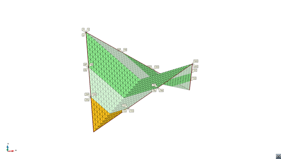
The following simple example shows the geodesic line generation for a four-point sail, separating the geometry in 6 parts (depicted by the differently coloured stripes). The separation into parts is done automatically. In a following step, these parts can be used for the cutting pattern generation

|
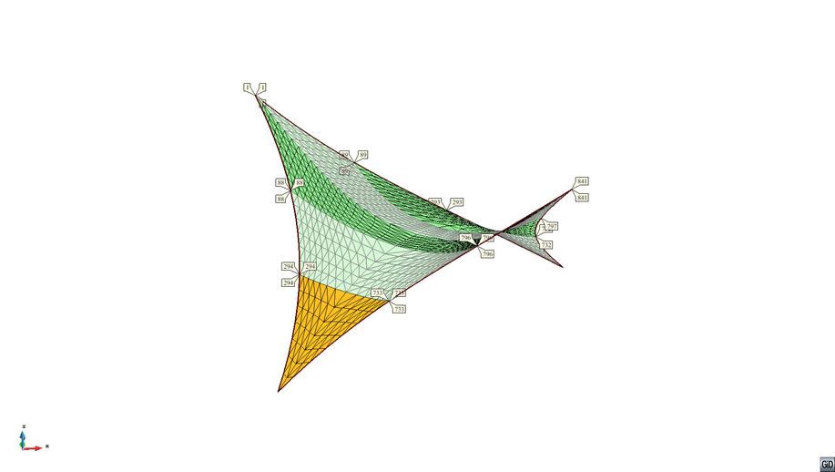
The formfound geometry with its separation into the different parts is shown in the picture below.

|
Benchmark Examples
- Four point sail with three geodesic lines (not included in benchmarks due to amount of time but working!) ...benchmark_examples\analyses\geodesic_membrane1_I\x_cbm_4_point_geodesic.txt
References
- ↑ Dieringer, F.: Numerical Methods for the Design and Analysis of Tensile Structures, Dissertation Lehrstuhl für Statik, 2014
| Whos here now: Members 0 Guests 0 Bots & Crawlers 1 |